")
")
- Details
- Hits: 23665
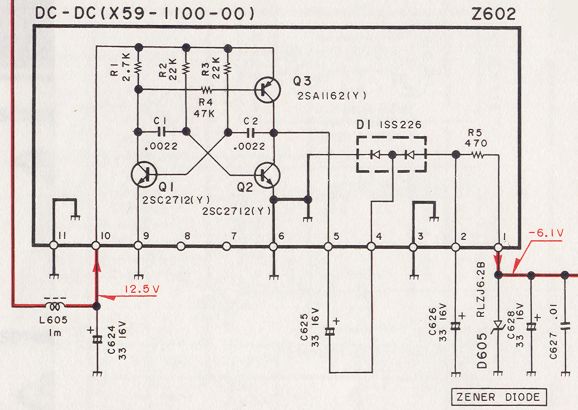
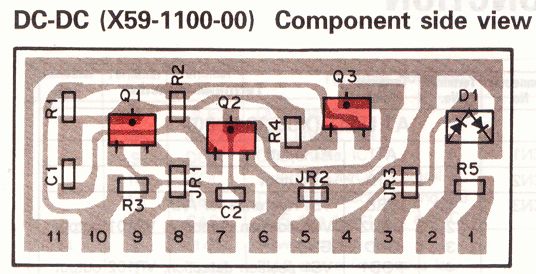
Pictures of diagram and board layout. (click to enlarge). Please note that capacitors C626 and C628 are shown reversed, but that they are correctly mounted on the board !
Symptom :
After several years of operation, the TS850 sometimes is presenting an instability in the transmitter output power. Power varies and drops after a few minutes, comes up again and stays low...
Analysis :
There are several possible origin for this problem, we are treating here only the instability due to an ALC problem, which is the most common. Other reasons are treated elsewhere on this site.
The RF-UNIT unit is divided in several boards, one of these is smaller than the RF UNIT main board and supports the ALC function. This board is mounted verticaly and has the part number X59-1100-00. This board delivers an ALC voltage of -6.1V derived from the main +12.5V. This voltage converter is built with a astable multivibrator using 3 transistors, and a full-wave rectifier with the help of 2 diodes. Two capacitors C626 and C628 are filtering the ALC voltage. The Zener diode D605 limits the output voltage to -6.1V
If you have a minimum of technical knowledge, you can repair this ALC board.
Repair :
Start in measuring the ALC voltage which should be close -6.1V on pin 1. This voltage should stay stable in time and when using the TX. If it's not the case, it's time to heat the soldering iron !
Start in replacing the resistors R2 and R3 from 22kOhm to 18 kOhm. Very often this modification is enough, in particular when the transceiver is operated with a low supply (12V).If this does not help, all other components can be incriminated, but experience has shown that mostly the transistors, diodes and capacitors are faulty. These capacitors are not located on the ALC board but on the main board ! Even if you do not detect any problem with them, it is wise to replace them beacause they mostly finish to leak or dry...
- Details
- Hits: 30644
Updated 2023 jan. 27
A newer and mature version with more options has been published. An EXE file is available.
While setting up my remote station, I quickly have been confronted to the problem of the limitations of the remote ease of use. The first one is the ability to change the VFO frequencies. My logging software LOGGER32 offers a lot of macros and an option to use the mouse wheel to change the frequencies. But during daily traffic or contesting they quickly have shown their limitations.
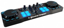
On Twitter, I have seen that several hams have been using a small DJ controller for driving SDR receivers and transceivers. So I started thinking to do the same for the TS590s.
- Details
- Hits: 20645
 I used the Cushcraft A3 et A4s yagis and soon or later, problems are appearing..
Here are the results of my investigations and repairing technic, that can be applied to other models and trades as well.
What is described here applies to a A4s triband antenna, but the reasoning can be made for any multi-band yagi or vertical.
- Details
- Hits: 45066
![]() For my SOTA activities, i recently bought a QRP transceiver QRP SW-3B, which is a three-band QRP CW only for 40/30/20 m.
For my SOTA activities, i recently bought a QRP transceiver QRP SW-3B, which is a three-band QRP CW only for 40/30/20 m.
So, i needed an antenna that would allow to use these 3 bands in SOTA portable activity.
Already having some experience with the EFHW antenna, i decided to build one for 40/30/20m.
The main advantages of this EFHW antenna are :
- easy to build
- multiband
- needs only one support, can be installed in line, inverted V, zigzag.
- fed at its extremity, can be directed connected to the transceriver, without any coaxial cable.
- the radiating part is at the center
All these advantages are welcome for portable operations and make this antenna a perfect candidate for SOTA
- Details
- Hits: 14267
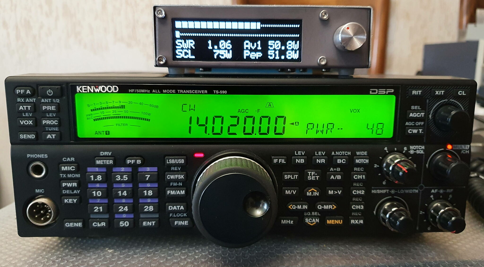 |
Wishing to replace my good old trusty BIRD 43 Watt-meter, I prospected a little on the Internet and found the description of an open source project for a Watt-meter which corresponded perfectly to my needs. This is a fork of the version made by TF3LJ, and developed by PD0LEW. A new hardware version was subsequently developed by WA2T. I chose the version with an OLED display, but there are versions with touch-sensitive TFT displays. |
- Details
- Hits: 7467
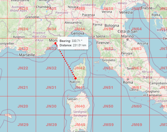 |
The last QRA locator map no longer uses any API functions or Google maps. From now on, the Leaflet API and free basemaps are used. New features have been added, such as: - search by QRA locator on 6 or 8 characters. - search by address, location. - a tool for measuring distance and azimuth |
- Details
- Hits: 1261
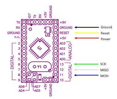 |
Petit tuto pour programmer un Arduino Pro-mini en ICSP avec un programmateur USBASP 2.0 Dans certains cas, il peut être nécessaire de programmer un Arduino via le port ICSP. Par exemple, si le microcontrôleur a été remplacé par un neuf, si par mégarde le bootloader a été corrompu ou effacé, si le programme injecté est corrompu et qu'il n'y a plus d'accès via le port USB ou le connecteur FTDI, si le logiciel est distribué au format HEX, si on n'a plus accès au microcontrôleur via le port USB, etc... |
- Details
- Hits: 1475
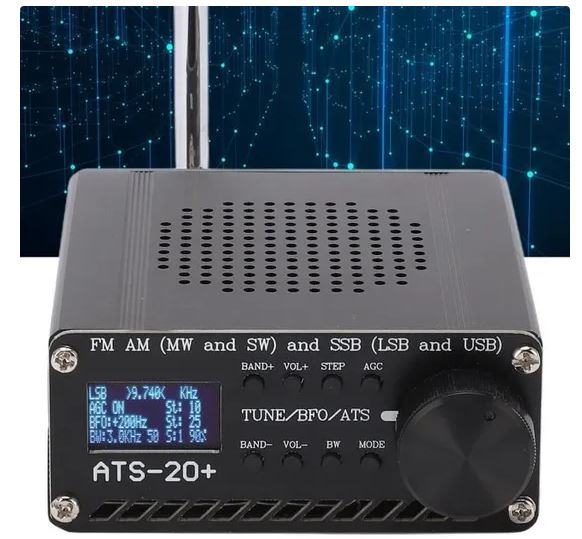 |
Le récepteur ATS20+ est une utilisation matérielle de la librairie pour le SI4735 écrite par PU2CLR pour l'Arduino. |
- Details
- Hits: 15879
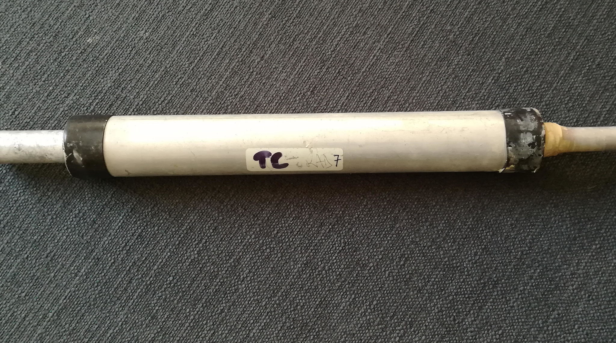
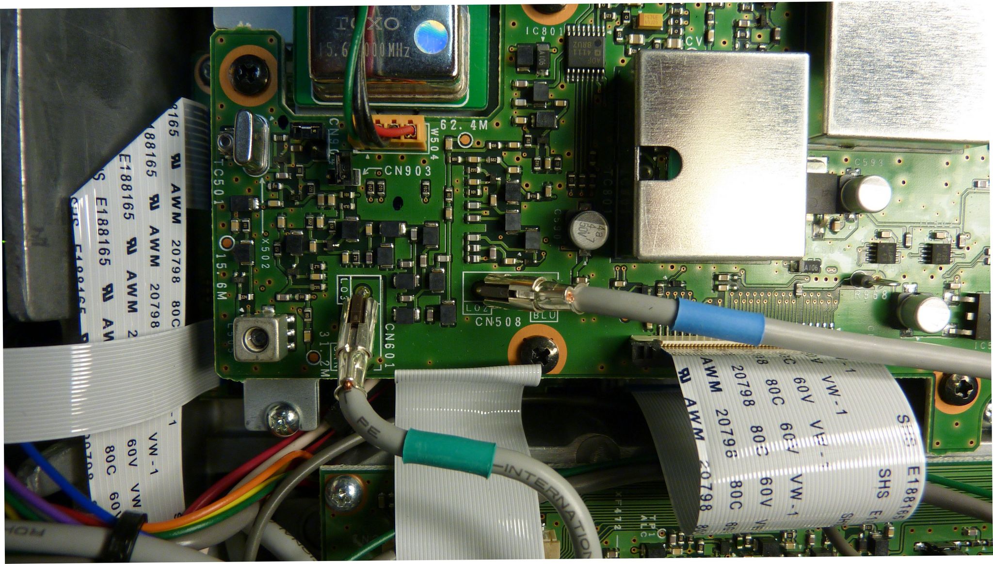
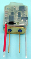 Based on an idea received from Ron VK6KDD, here is the description of a cheap TCXO for your TS850 which improves stability a lot, within +/- 4 Hz. It can also be applied to any other rig using a reference crystal.
For about 12 €, you can find a precision crystal heater at Kuhne Electronics by DB6NT. This precision crystal heater provides temperature compensation for crystals, usually found within crystal oscillators. The assembled circuit, which is built on AL2O3 ceramic substrate, should be mounted against the thermostat crystal using heat shrink tubing. The circuit heats the crystal to a temperature of 40.8° C with an accuracy of better than 0.1° C. This provides high frequency stability over the temperature range of -5 to +40° C.
The use at 40°C permits to use standard Xtals, so no need to have a special Xtal. If your rig heats a lot or if you live in very hot countries, this addon will help you only if your rig stays under 40°C working temperature.
.
- Details
- Hits: 22846
 Since the beginning, my brand new TS590s had a intermittent problem. The reception was fading and sometimes disappeared completely. Sometimes, the TX went away and at the same time, the HI/SHIFT setting didn't work above 3000 Hz.
I noticed that a slight shock on the case brought the rig back to live, but not always. Being new and under warranty, i sent the rig back for repair.
Subcategories
Test equipements Article Count: 5
Antennas Article Count: 8
TS850 Article Count: 4
TS590 Article Count: 3
Cartes Article Count: 2
Radiosondes Article Count: 1
- Kazançlı bir başlangıç yapmak için deneme bonusu sunan bu siteye göz atabilirsiniz.
- Fırsatlarla dolu deneme bonusu veren siteler arasında öne çıkan bir seçenek burada.
- Yeni üyeler için özel bonus veren siteler, avantajlı teklifleriyle dikkat çekiyor.
- Kullanıcı memnuniyetine odaklanan bonus veren siteler, eşsiz fırsatlar sunuyor.
- Güvenilir bir deneyim için deneme bonusu veren siteler, kazanç kapınızı aralıyor.
- Hızlı kazanç fırsatı sağlayan deneme bonusu seçeneklerini keşfedin.
- Avantajlı teklifleriyle deneme bonusu veren siteler, yüksek kazanç imkanı sunuyor.