")
")
- Details
- Hits: 15530
Some notes on how to use a SIM800 coreboard with an Arduino.
I bought the following cheap SIM800L board and have had some problems to make it work.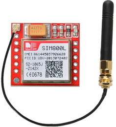
- Details
- Hits: 24252
Description of a PCB, also called "shield" allowing to build a universal rotator interface based on the K3NG software. Only the AZIMUT function is supported.
This PCB has been thinked to be used either with a LCD display or an Ethernet shield to allow a remote usage via IP, and for a rotator using a variable resistor for the azimut value . (HAM IV or CD44 in my case)
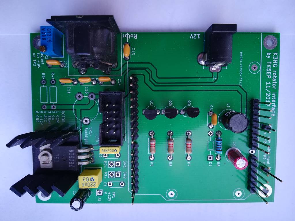 The board includes :
- a 5V/1A regulator
- a header to plug an Arduino UNO and an Ethernet shield
- a HE10 male connector for to LCD display with a ribbon cable
- a 5 pin DIN connector (+ ground shell) to connect the rotator control box
- 2 connectors for the "Clockwise" and "Counterclockwise" pushbuttons
- a multi-turn ajustable resistor VR2 for the azimut calibration
- an ajustable resistor VR1 for the LCD contrast
- 3 transistors for the CW, CCW, and BRAKE commands (open collector outputs)
I still have some naked pcb boards left. If interested, please feel to contact me.
- Details
- Hits: 4043
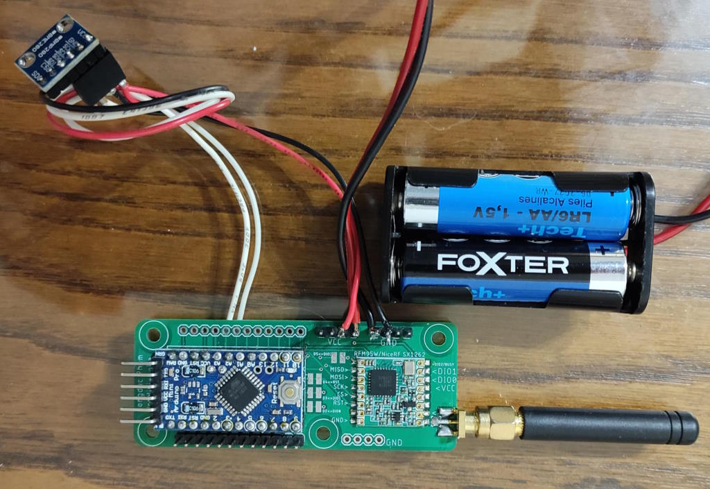 |
Having gained some experience with my weather station project described in the APRS LoRa weather station article, and having a few LoRa RFM95W modules, I decided to carry out a feasibility test for a very low-power mini weather station. The initial results were very encouraging, so I continued my project until I had a mature design. |
- Details
- Hits: 69554
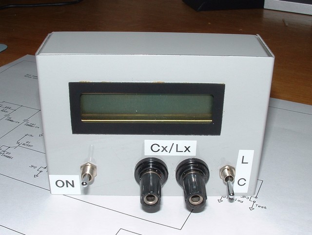
Here is the description of a simple capacitance and inductance meter, easy to build, based around a PIC microcontroler. Simplicity does not mean poor characteristics. The precision is very good and even better than many commercial LCmeter !
The original description has been done by Phil Rice VK3BHR on his pages. I only did adapt it to my needs.
Here are the main characteristics :
- measures from 0 to 838 nF and 0 to 83.88mH.
- precision +/- 1%
- printed board eliminating any connecting wires.
- use of common case (at least here in Europe).
- use of common components.
- Details
- Hits: 16819
Voici un simulateur pour le populaire coupleur d'antenne en T avec capacités série et inductance parallèle. Les trois boutons au bas du dessin permettent d'ajuster les trois composants. Ils peuvent être réglés en déplaçant la souris sur un bouton, en cliquant et en maintenant le bouton gauche de la souris appuyé et en faisant tourner le curseur autour du bouton. Le bouton devrait alors tourner et faire varier la valeur du composant choisi. Les boutons des condensateurs ont une course de 10 tours et la self 30.
| No java |  |
Le ROS est affiché simultanément de manière digitale en haut à gauche du "coupleur" ainsi qu'analogiquement sur le ROS-mètre. La perte provoquée par le coupleur est affichée en pourcentage par rapport à la puissance d'entrée ainsi qu'en dB. En cliquant sur le bouton "Autotune", l'ordinateur calculera la valeur exacte des composants qui adapteraient parfaitement la charge en limitant au minimum la perte dans le coupleur en supposant que les condensateurs variables ont un Q nettement plus élevé que la self.
L'algorithme de calcul Autotune tente de minimiser la valeur de l'inductance à utiliser en commençant par essayer de trouver un accord en affectant une valeur maximum à un des condensateurs variable, puis si cela échoue, il essaye chacun des composants avec sa valeur actuelle. Si aucun accord initial n'est trouvé, il abandonne et affiche "Tune failed" dans le panneau des messages. Si un accord initial est trouvé, il effectue une recherche dichotomique entre la valeur de départ de l'inductance et zéro afin de trouver la valeur minimum de l'inductance pour un accord.
Notez qu'il est simple de programmer un algorithme qui trouve le minimum de perte, alors que nos coupleurs n'ont pas d'indicateur de perte, une règle comme "trouver un accord avec un minimum de self" est bien plus utile. Dans tous les cas, le Q des véritables composants varient pendant qu'ils sont ajustés.
Le bouton Set Up vous permet de changer la valeur maximum des trois composants et leurs Q. Initialement les condensateurs ont une valeur de 250pF, un Q de 2000 et la self une valeur de 30 uH et un Q de 100.
Les trois champs à droite vous permettent de changer la charge et la fréquence en MHz.
Une façon d'utiliser cette applet est de sélectionner une valeur de résistance et réactance de la charge, puis d'ajuster les boutons pour trouver une adaptation, comme vous le feriez avec une vrai coupleur. Notez le pourcentage de pertes dans le coupleur pour votre réglage et cliquez ensuite le bouton "Autotune" et vérifiez si l'ordinateur a trouvé un meilleur réglage.
Veuillez prendre note que si vous cherchez un logiciel pour déterminer les valeurs optimums des composants d'un coupleur en T, vous devriez chercher ailleurs !
Pour utiliser ce logiciel localement sur votre ordinateur, téléchargez le fichier tuner.jar et le fichier que vous visualisez actuellement tuner.html et copiez les dans le répertoire de votre choix, puis visualisez le fichier tuner.html à l'aide de votre navigateur.
Le code source Java de l'applet est distribuée sous licence GNU general public. la source est disponible dans l'archive tunersrc.zip.
La page de l'auteur est disponible ici. Vous y trouverez quantité d'informations intéressantes d'un niveau technique parfois élevé !
- Details
- Hits: 4514
 |
Lilygo LoRa modules from Lilygo are advertised to provide a power output of +20dBm (100mW). I found that none of my modules reached the advertised power, which was more like +17dBm. |
- Details
- Hits: 37643
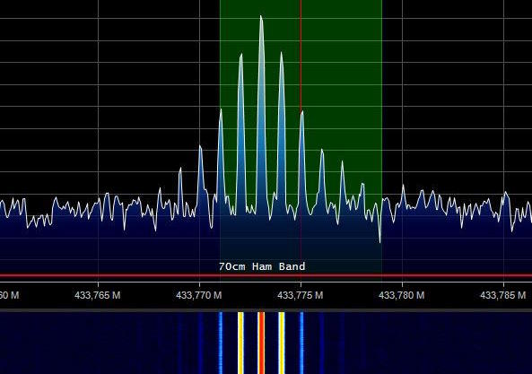
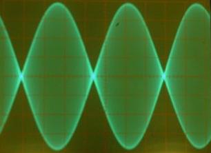 The orinality of this description is that the tone generation is made by the use of a DDS and not a sine wave generator made with transistors or a special circuit. It also does not use any special and expensive component but only junk box components, or at least cheap ones !
The main characteristics of this generator are :
- Two tone generator 800/ 1000 Hz or 400/2600 Hz (jumper selectable)
- Single tone generator of 1000 Hz
- Ajustable output level, max around 100 mV pp on 600 Ohm, or 35,4 mV eff. in single tone or 25,0 mV eff. in 2 tones
- Spectral purity between 0,3 and 150 kHz > 50dB !
- Distorsion <0,01% (in single tone) !
- Supplied by a 9V battery, consumption 7-8 mA that gives 50 working hours with an alcaline battery.
- Automatic PTT switching at power on.
This circuit has originaly been described by DH7AHN ,adapted and translated by myself for my usage. The original description can be found here
- Details
- Hits: 39539
This page has no pretention and is not a complete description of the vertical antenna, it only is intended to help you understand the most important things about this antenna and to how make it work !
 The simplest of all antennas is the vertical, also called the Marconi antenna. It has a quarter wave electrical length and has its base connected to earth.
This antenna vibrates with a intensity node (minimum) at his top, so at a voltage antinode (maximum).
Simple in its operation, it is by cons not the easiest to understand and handle.
Picture : The 1/2 wave antenna and it's equivalent mounted on ground. The missing 1/4 wave can be considered as its image in the ground.
 A PERFECT1/4 wave vertical would have at its resonating frequency the following characteristics :
- No horizontal radiation
- 5,1 dBi gain
- Maximum radiation at 0°
- Impedance of 36,5 Ohm
- No loss in the grounding system
PERFECT means no loss in the vertical radiating part, no loss in the grounding system (also called counterpoise, by analogy to mechanics)
In these conditions, with a 50 ohm coaxial feedline, you should accept a 1.4 SWR or add a matching system with a quarter wave line ot a LC circuit.
 Unfortunately, perfection does not exist...
Consider the same antenna over the best earth that can be found : salt water (i know it's stupid)
The diagram already shows a visible difference :
- Maximum radiating angle : 10°.
- Gain loss : 4,45 dBi
- Impedance 36 Ohm.
This difference is due to a worse soil conductivity.
 The same antenna, but this time over a bad soil (city lot). I don't wish that to anybody !
The diagram shows :
- Maximum radiating angle at 28°.
- Important loss : -1,01 dBi
- Impedance 36 Ohm.
We see that the soil nature is very important for this antenna !
![]() The efficiency of a vertical depends not only of the soil nature, but also other factors. Considering losses, the efficiency can be resumed by the formula :
The efficiency of a vertical depends not only of the soil nature, but also other factors. Considering losses, the efficiency can be resumed by the formula :
- Losses in the loads (coils, traps, etc...)
- Losses in the ground
In ground losses, we have to consider TWO TYPES of loss :
1) The ground at immediate antenna vicinity in which the current return will be done.
The power applied to the antenna has still not been radiated and the losses are dissipated in the ground and are reducing the radiatiing efficiency of the antenna.
2) The ground all around the antenna over a large number of wave length, typicaly > 2 for a quarter wave vertical.
It is in this part of the ground, called Fresnel zone, that the power radiated by the antenna will be reflected by the soil and will contribute to the reflection efficiency.
We see that for having an efficient vertical antenna, we can act on these 2 factors. If it is almost impossible to influence the second one (you can move to a remote island, water your garden), we can improve the first one in reducing the losses to their minimum.
With a poor ground and in order to have the best current return as possible, we can reduce the losses by placing a certain amount of radials.
These radials can be :
- laid on the ground.
- buried into the soil.
- raised over the groundl.
The first 2 methods are equivalent in terms of performances, except if you are burying the radials too deeply. Depth from a few cm to several tens of cm will not make a big difference.
Brown, Lewis and Epstein in their 1937 studies have shown that in order to obtain a perfect grounding system, 120 radials are needed !
Less radials means worse efficiency, more will not bring an improvement.... A reasonable minimum would be 16 radials of a 1/8 wave length.
Curiously, the number of radials also determines their length. The follwing table gives this relation :
| Nb radials |
4
|
12
|
16
|
24
|
48
|
96
|
120
|
| Length (Lambda) |
0,1
|
0,15
|
0,125
|
0,25
|
0,35
|
0,45
|
0.50
|
 In all cases were 120 radials are not possible, it is better to use surelevated radials.
Computer simulations and real-world tests have shown that 6 radials of 0.25 wavelength uniformely disposed around the vertical give the same result as 120 radials of 0.5 wavelength !! Only one radial is altough enough for a good current return, but the antenna will have a certain directivity and a horizontal component.
2 radials are correcting this.
CAUTION, using surelevated radials will lower the impedance down from 36 Ohm to close to 21 Ohm !!
The radials must be tuned in order to reduce the radiation impedance. Their height over ground should be at least 0.03 wavelength, but this heigth depends of the soil quality. The poorer the ground, the higher the radials.
The best would be to elevate the base of the vertical in order to strain the radials at 90° (horizontaly). The higher the antenna, the better the gain.
When all this is not possible, the radials are placed at 45° from the base until they reach the right heigth and the rest will be strained horizontaly.
Some practical hints :
- I'm tuning the radials by pair (in opposite directions) in connecting them like a dipole and with the help of a noise bridge or a VNA placed at the base of the vertical. The important fact is tuning them to the right frequency, not for lowest SWR. Once tuned, they are reconnected at the antenna base.
- Use good insulators at the end of the radials, they have a maximum of voltage at this position. I've seen insulators of several cm taking fire under wet conditions !
- When using plastic insulated wire for the radials, you have to cut them shorter by 4 - 6% as the theoretical length.
- In case of lack of space, you can shorten the radials by placing coils (with some additional losses...) or bend their extremities.
- A vertical works well on a flat, clear and uniform ground.
- Details
- Hits: 37478
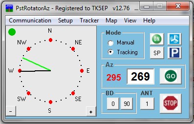 |
While building up my remote station, i was looking for a solution to control one or 2 azimuth only rotators via the Internet. There are several solutions and i finally adopted the K3NG rotator project i already used for a rotator controller connected via USB to my computer. |
- Details
- Hits: 64600
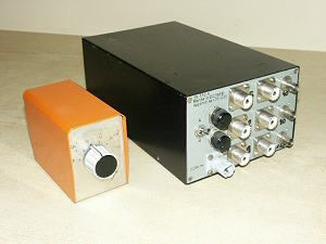 During our multi-multi contest operation, we came against a problem while using low band receiving antennas.
There were 3 low band stations, one on 160m, another on 80m and one on 40m.
The problem was simple : how could we share the Beverage antennas on all of these 3 stations ?
The first solution was to split each antenna in 3 directions with coaxial T's and to use a coax switch on each station, so that each station could select a different antenna. That proved to be not very satisfying, the impedance seen by the receivers and antennas were changing a lot depending on the position of the different switches.
DK4VW, Uli told me that the BCC (Bavarian Contest Club) crew was using a Beverage switching box that proved to be very efficient and i began to build such a box with his precious help.
Informations below given with permission of DK4VW.
- Details
- Hits: 14470
During the writing of my beehive monitoring project "Apaguard " using an Arduino UNO, i've been quickly very clode to the SRAM limit...
The Arduino UNO has "only" 2048 bytes of SRAM, which can quickly be filled if no precautions are taken.
Here are a few tricks i used during my writing, which permitted me to save a lot of SRAM and should be used by anyone coding on Arduino.
Subcategories
Test equipements Article Count: 5
Antennas Article Count: 8
TS850 Article Count: 4
TS590 Article Count: 3
Cartes Article Count: 2
Radiosondes Article Count: 1
- Kazançlı bir başlangıç yapmak için deneme bonusu sunan bu siteye göz atabilirsiniz.
- Fırsatlarla dolu deneme bonusu veren siteler arasında öne çıkan bir seçenek burada.
- Yeni üyeler için özel bonus veren siteler, avantajlı teklifleriyle dikkat çekiyor.
- Kullanıcı memnuniyetine odaklanan bonus veren siteler, eşsiz fırsatlar sunuyor.
- Güvenilir bir deneyim için deneme bonusu veren siteler, kazanç kapınızı aralıyor.
- Hızlı kazanç fırsatı sağlayan deneme bonusu seçeneklerini keşfedin.
- Avantajlı teklifleriyle deneme bonusu veren siteler, yüksek kazanç imkanı sunuyor.