")
")
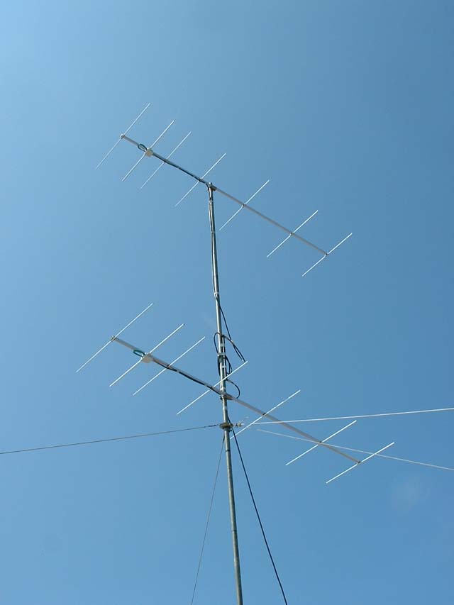 Since almost 30 years, for my portable VHF activities, I used a F9FT 9el yagi. This one was the best available for this purpose, it was leigthweight, relatively cumbersome and performed quite well. Unfortunately, it broke during a contest when falling down from 7m high...
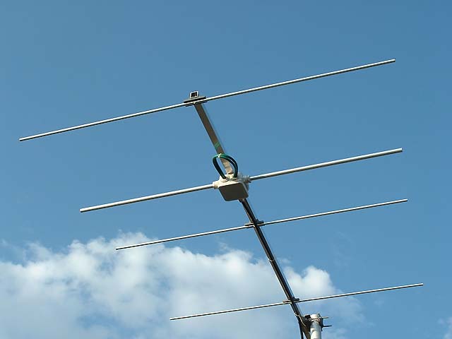
To replace my beloved antenna, I decided to build something and not to buy one. After searching some design on internet, I finally adopted DK7ZB's one. He offers several designs, and iIchosed a 7 element yagi in 28 Ohms technology.
The advantages of DK7Zbs antennas are :
- Computer optimized
- Great reproductibility
- Easily assembled and dismantled. Ideal for portable operations.
- Excellent electrical characteristics, gain, pattern, F/B ratio.
The original version described on DK7ZB's page has a 3.26 m boomlength. So, I asked him if he could calculate it for a 3m boom. Aluminium tubing are sold in 6m length, and with 3m booms i would be able to build 2 antennas. The new calculated antennas have a small gain drop (about 0.35 dB)
Another advantage of this 7el is that with a 6m long alu tubing, you have enough for all elements and build 2 antennas.
The new antennas have the following characteristics :
- Antenna length 2.98m, fits on a 3m boomlength
- 10.70 dBd gain
- F/B radio > 30 dB, clean pattern
- Excellent impedance match
- Short vertical spacing for stacking
Electrical characteristics :
The author DK7ZB chosed to calculate his antennas for a 28 Ohm impedance for different reasons compared to a 50 Ohm version :
- broader bandwidth
- better radiation pattern
- simple and efficient electrical match, no gamma or beta match
- easy mechanical design, no folded dipole
The elements are insulated from the boom allowing a greater reproductibility. The computer calculated lengths of elements can directly be mechanically applied. Indeed, elements mounted through the boom have to be shortened by an amount depending of the respective diameter of elements and boom, frequency, etc....
The part of the element crossing the boom is "short circuited" by an amount... This factor of correction has been studied by DL6WU and he gives a formula to calculate that.
The mechanical assembly of the elements on the boom is done by a screw through the center of the element to the boom. The centers of the elements being at a very low current level, the insulator and screw have no electrical influence on the electrical length.
The antenna beeing designed for a 28 Ohm impedance, a match has to be used for a perfect 50 Ohm match.
The easiest and most efficient way to do this is to use a quarter wave length of adequate feeding line. To calculate this impedance the formula has to be used :

Where Za = adaptor impedance, Ze = input impedance, Zs = output impedance
In our case, the calculalted value is 37.5 Ohm. Coaxial lines of this impedance are not sold, we have to build it... Putting two 75 Ohm lines in parallel will do the match !
Now you understand why DK7ZB chosed this odd 28 Ohm impedance to build his antennas !
The electrical length of the quarter wave line is, in our situation : 144.200 Mhz => 0.519 m
The mechanical length of the adapter depends of the nature of the coaxial cable chosed. Waves travelling through a dielectrical other than vacuum are slowed down by a factor depending of the nature of this dielectrical. This factor is called velocity factor.
Here are the velocity factor for dielectricals used in common cables :
Teflon : 0.70
Polyethylen : 0.66
Foam Polyethylen : from 0.70 to 0.80 !
Note that CATV coaxial cables have an aluminium shielding which can't be soldrered, making them difficult to use in our case.
For the RG59 (or KX6) cable i used, the mechanical length is 0.519 m * 0.66 = 0.343 m.
CAUTION : This length is from tip to tip of the shield !
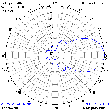
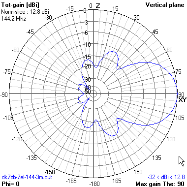
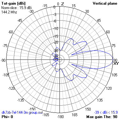
Here the diagrams of this antenna, calculated with the excellent freeware 4nec2 available here.
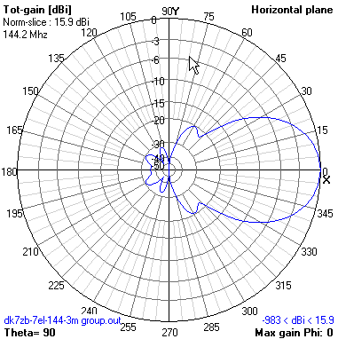
If you want to stack 2 of these antennas, the optimum stacking distance is 2.90 m. Here the corresponding diagrams.
The announced gain does not include losses in phasing lines and coupler.
Construction :
The antenna is built with 8mm elements and the radiator is 12mm thick, boom is 20x20mm.
Using thick elements makes the antenna a bit broader and mechanically a bit more tolerant.
You MUST use these diameters if you want the antenna to work. Using other diameters would need a new calculation and other element lengths !
| Réf (8 mm) | Rad (12 mm) | Dir 1 (8 mm) | Dir 2 (8mm) | Dir 3 (8mm) | Dir 4 (8mm) |
Dir 5 (8 mm) |
|
| Espacement | 0 | 325 | 560 | 1035 | 1665 | 2405 | 2980 |
| Longueur | 1030 | 970 | 942 | 921 | 908 | 915 | 890 |
The insulators used to assemble the elements on the boom can be built or bought. DK7ZBs home page links to DM3MS Web shop where you can find all needed materials.
Another economical solution is describedhere by 9A4QV. I used a home made solution.
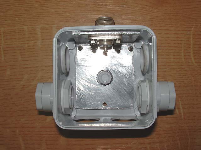
The dipole is built using a plastic box and needs some explanations.
The length is ment from tip to tip, including the space in the middle ! I made this spacing 10 mm large. Add some mm at each end of the radiator, in order to fine tune the antenna. (see tuning paragraph)
For the mechanical construction, the following pictures will help you. The box i used below is not the best for this purpose, a single hole in the center of the box for the coaxial adaptor would have been better.
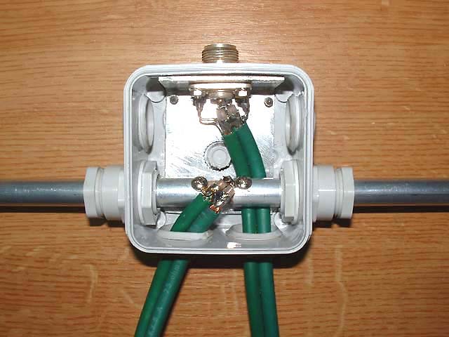
You can see the simple method i used to make the radiator rigid and tight. Any other method is possible and you can adapt it.
The N type connector MUST be grounded to the boom, what i did by adding an aluminium angle of which the connector is mounted. 2 larger screws are maintaining this angle to the boom, making a good mechanical and electrical fixing.
The insulator used in the center of the radiator is a piece of wood. Other and better materials can be used.
The coaxial adaptor has to be connected to the radiator and connector using the shortest possible leads.
 |
 |
 |
Building the antenna should not be a problem, the most difficult for me was the correct positioning of the radiator box on the boom.
For an easy transportation, i cut the boom in 2 parts, at exact gravity center (including weigth of coaxial feed line), and it turned out to be at 1.24 m from rear. CAUTION : cut the boom BEFORE drilling the holes for the elements, you can lose as much as 1mm in sawing it.
If the antenna is not intended to be used in portable operations, keeping the boom in one length will give you more rigidity.
I used mouting clamps recovered from old F9FT antennas.
Tuning :
Before connecting the radiator, it is wise to check the coaxial adaptor.
For this, i loaded one end of the quarter wave length with two 56 Ohm/2W resistors in parallel (which gives 28 Ohm). I checked SWR with my SWR meter tuning across the whole 144-146 MHz band.
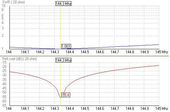
Once finished and erected at a few meter heigth, you can check the SWR, find the minimum which is rather broad and should be too low in frequency (remember the few additional mm). You can now precisely tune your antenna on the right frequency. Here the calculated values which turned to be the reality.
 |
|
Fig : SWR and RL simulated at resonance and Z=28 Ohm. Excellent !
|
 |
|
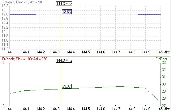
Fig : Gain (in dBi) and F/B ratio
|
For your calculations and simulations, here is the NEC file i used with the following excellent freeware 4NEC2 available here.
Good building and have fun !
Thanks to DK7ZB for his advices and calculation.
Many other antennas are described on his page, and since my request, he added a 3m boom version with slighty different dimensions he gave me.