")
")
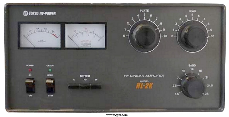 |
The TOKYO HIGH POWER RF amplifier HL-2K is an RF amplifier using two 3-500Z valves that is working on all ham bands, including WARC. It is well built and is a nice looking amplifier, but has some problems and needs some improvements. |
I've been given two of these amplifiers, one working and the other one not.
The serial numbers are close 603456 and 603524, but they differ a little bit. The case color are not exactly the same, the lowest serial number doesn't have the R103 anode glitch resistor.
After inspection, it appears that the broken amplifier suffered a lot. The fan didn't turn and the previous owner didn't notice that and continued to use the amplifier.
The problem was the SSR (solid state relay) RL3 which was burned. I ordered a replacement. (Panasonic AQ2A2-ZP3/28DC)
The excessive heat broke both tubes, and it was noticeable that some components overheated.
The bias diode D13 was broken, way to high idling current. Some RF capacitors in the plate output circuit were exploded, etc, etc...
After repairing both amplifiers, I've done some mods and corrections.
SWR problem
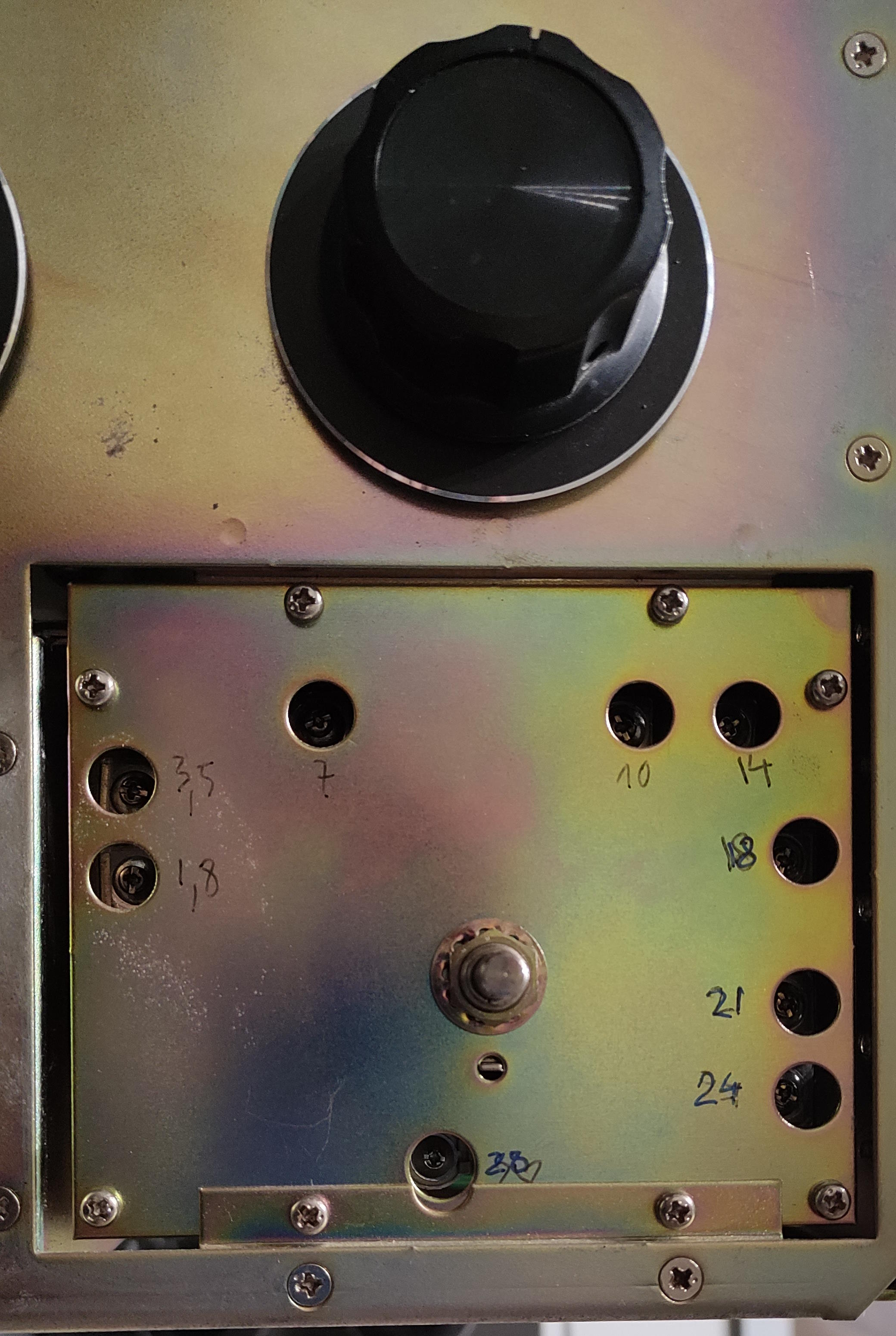
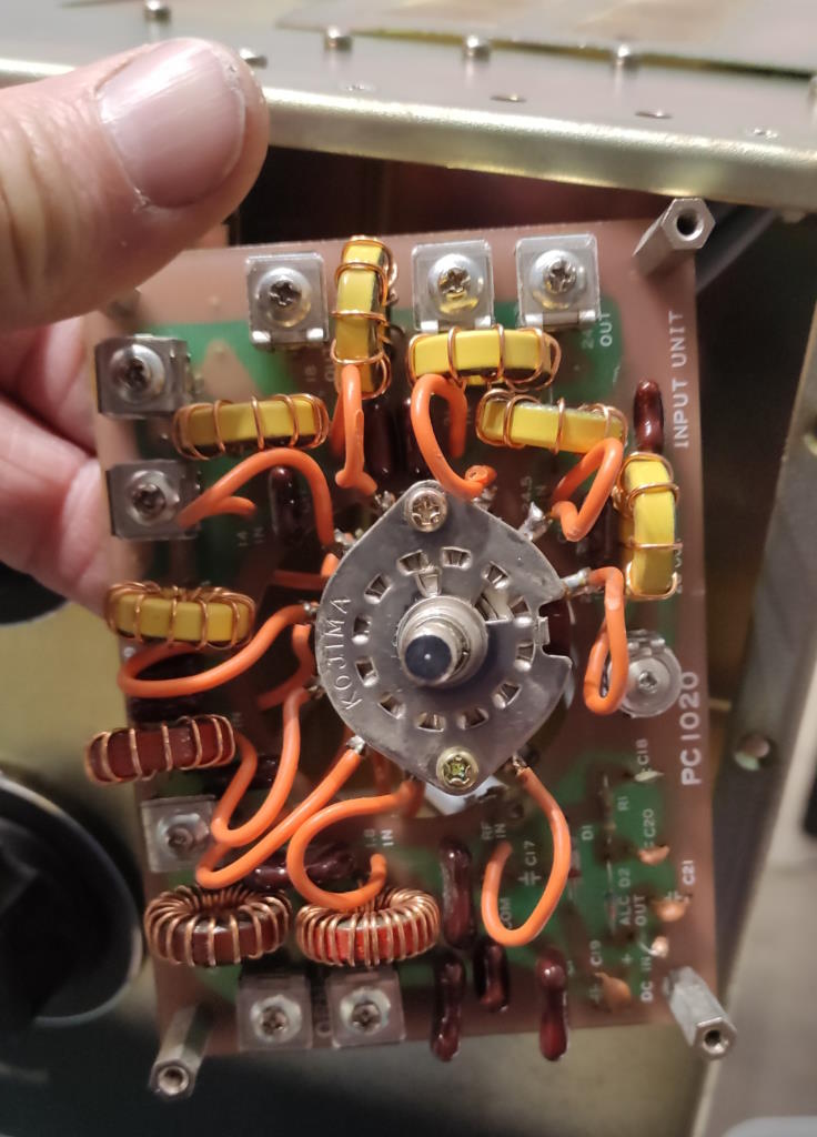
On both amplifiers, i had a high input SWR on the 21 and 24 MHz bands with no possible tuning with the corresponding variable input capacitors.
After a lot of searching, I found that the coils L7 (7 turns) and L8 (9 turns) were inverted !
After swapping them, I had a good tuning and low SWR from 1 to 1.1 on both amplifiers.
 |
 |
Power loss on the low bands
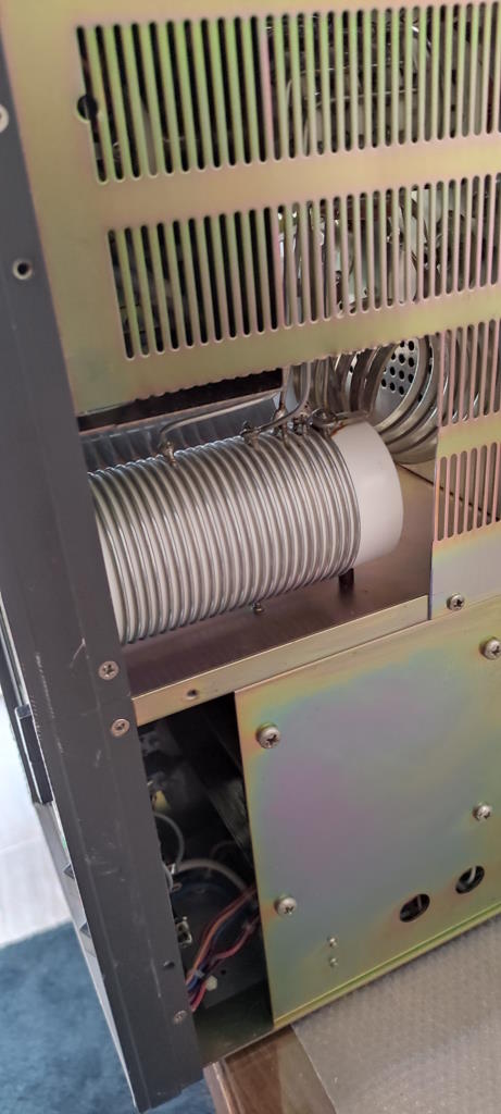
While repairing the amplifiers, I noticed that I had a very different Tune/Load capacitors setting and power loss on 160 and 80m once I put back on place the lower shielding.
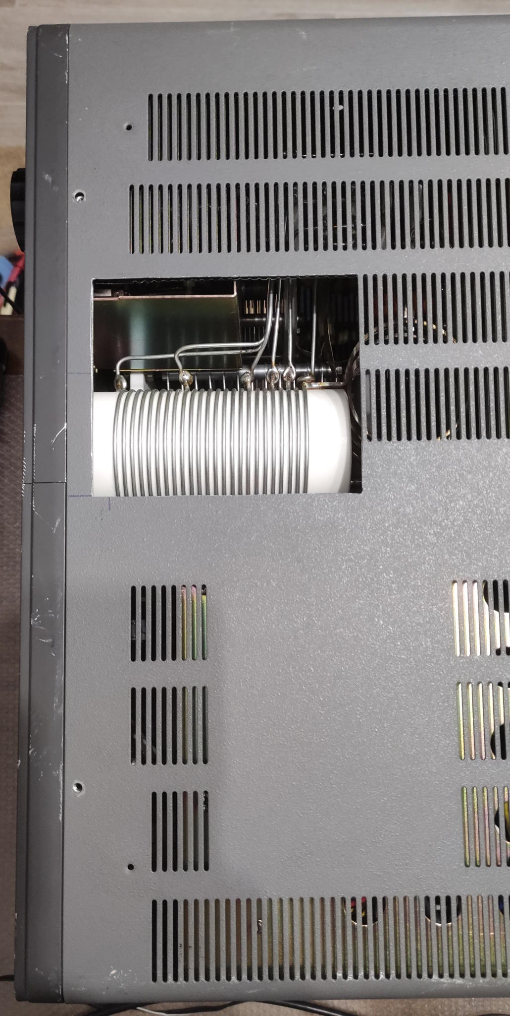
The problem is the position of the plate coil L11 which is much too close to the chassis and there is a big detuning and heavy currents are circulating in the chassis.
While transmitting, putting the plate on the chassis, causes sparks and a quick heating of the plate !
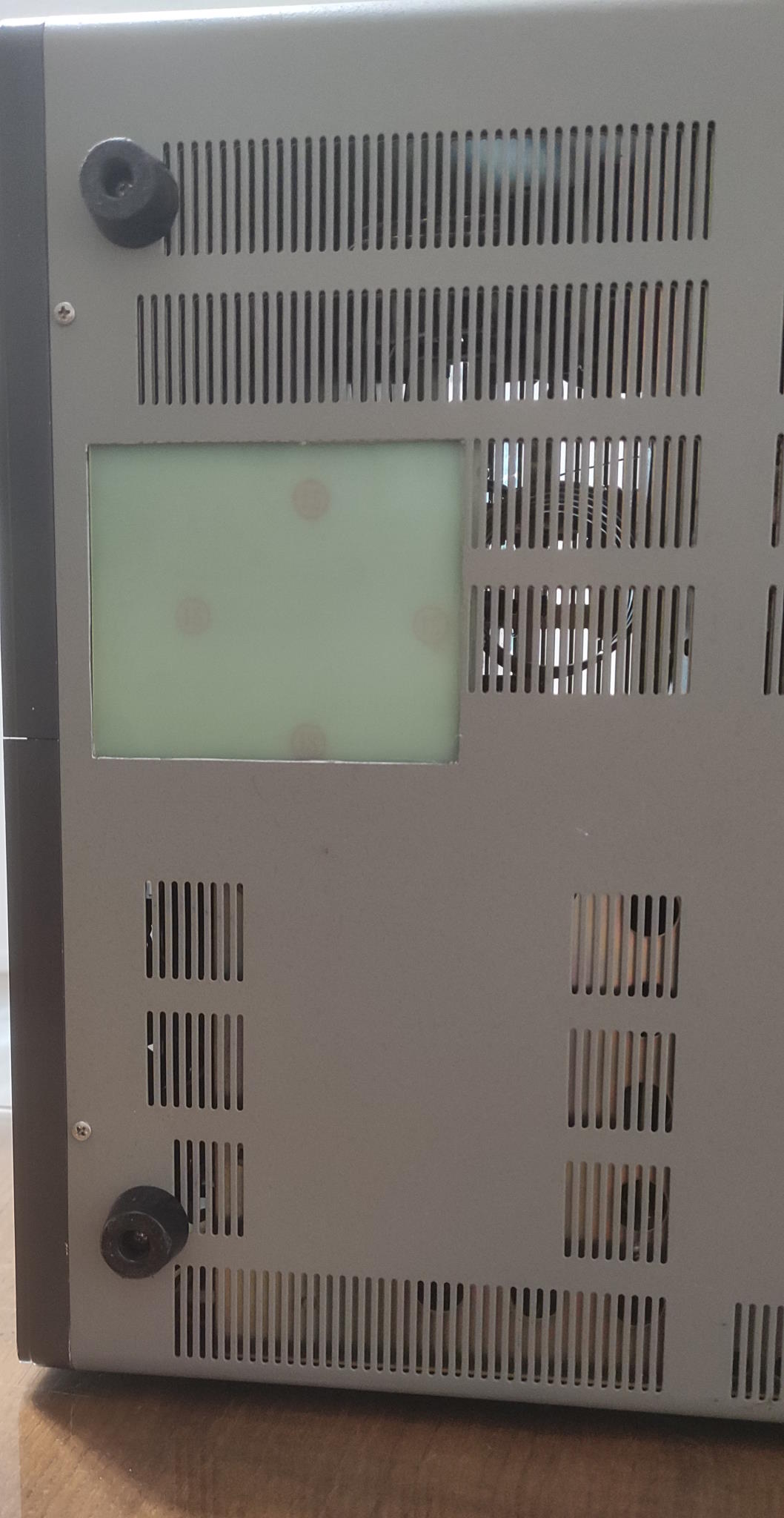
Solution: I made a large cut in the lower shielding as well as in the lower half of the case in order to move away any metallic surface form the L11 coil.
A plate of epoxy (pcb with copper removed) is closing the hole for security reasons.
After that, there is no more noticeable detuning and loss. BUT there is still some chassis heating on 160m. There is nothing that can be done against that without changing the L11 coil position. This is clearly a bad design problem and would need a big rework !
 |
 |
 |
Meter lamp replacement
On the 4 meter lamps, 3 were burned.
I replaced them with white LEDs that are wired in parallel (can be done if the Leds are of same model) and powered through a voltage droping resistor.
The blue wire that supplies the old lamps is removed from the anode of D6 (AC) on the PCB installed on the PA side, to the cathode to get a DC supply. With my Leds, I had to use a 820 Ohm for a 15 mA current.
The LED position needs some testing to find the best meter illumination.The final result is a nice looking amplifier illumination.
Step-start
The HL-2K has no step-start which is a pitty for such a nice amplifier, but is also very rare on other models too.
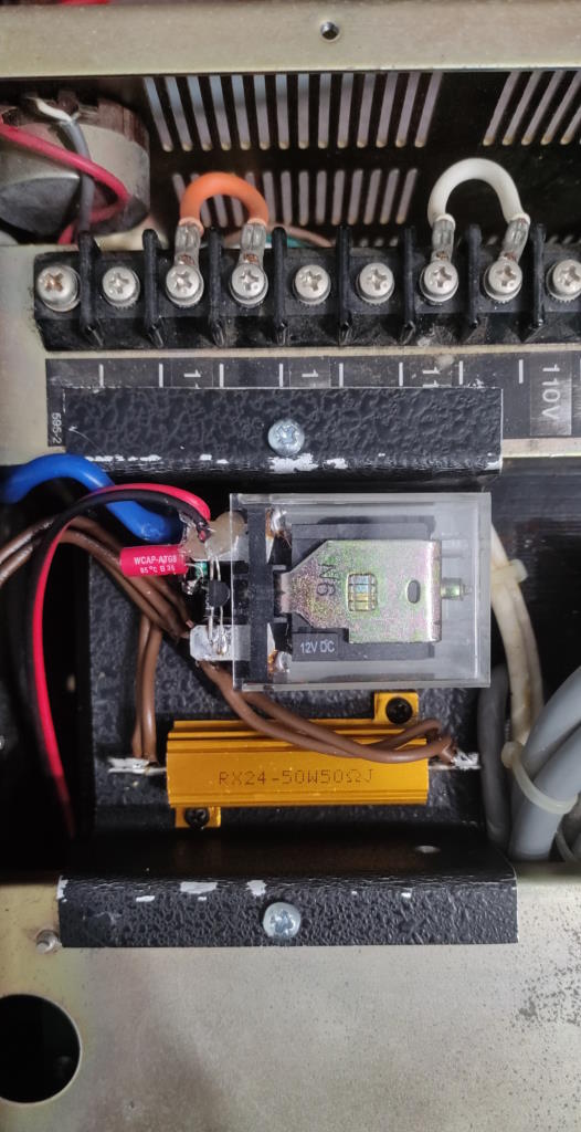
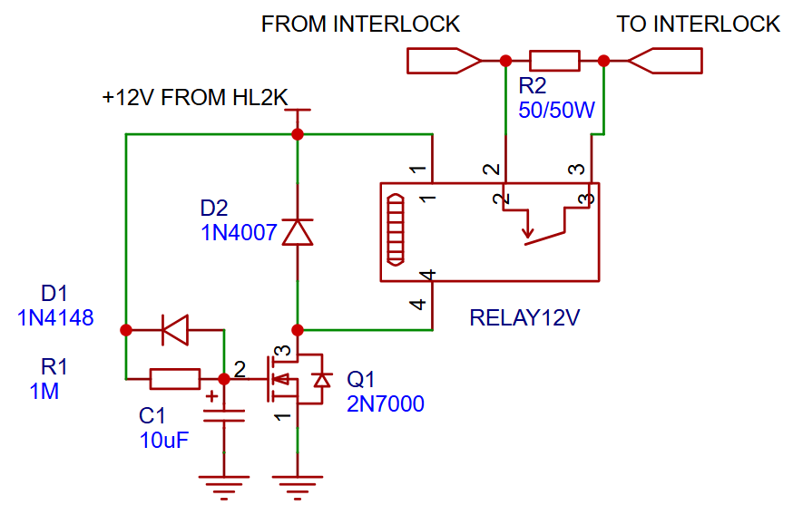
I've added a simple circuit that puts a 50 Ohm/50W in series in the AC power line for a few seconds.
This way, the inrush current is much lower, the valve filaments are protected and there is less stress on all HV PSU components during power ON.
It has been placed over the high voltage transformer on a small aluminium plate that I bent in a U shape so that it leaves some space to place the relay.
The relay is a 12V model with a heavy 25 A contact. 16A should be enough to be safe. My relay is activated with about 7.5V.
I wired all components in "Manhattan style".
 |
 |
Fan delay
The fan, driven by an SSR (solid state relay), is blowing a certain time after power off in order to cool down the tubes.
On my amps, it had a delay of about 50 seconds. The manual says 120 seconds.
Solution : I've put a 6800uF capacitor in parallel with C113 to allow a longer delay. After that modification, the fan is blowing at least for 150 s.
Tube replacement with QB4-1100
Both 3-500Z on one amplifier where broken, the anode was hanging and moving around, probably due to excessive heat.
I didn't want to pay a fortune for new 3-500Z. I have a stock of old new QB4-1100 tubes, that are tetrodes and I wanted to test how they work in grounded grid as a direct replacement.
On the HL2K tube socket, the grids and unused pins are wired to ground with a large braid. Perfect ! The screen of the QB4-1100 is grounded without doing nothing !
I removed the wire arriving on collector of Q1, to remove completely the grid polarization voltage. (D11 being broken, it didn't repair the circuit at all)
After taking some precautions (tube regenerating) I did put the QB4-1100 and did let the tube heat for about 24h without any HV applied.
I then connected the HV and nothing happened, no bang, no fuse burning, that was good !
The idling current was close to 100 mA and was stable.
Applying some RF power, everything was reacting normally and with 100W drive power, I could get 1100W on 14 MHz, which is a bit less then with the 3-500Z.
The QB4-1100 have less gain then the 12-13dB gain with a pair of 3-500Z.
Only the 160m band was giving a bit less power, about 950W. (see above chapter about the power loss problem)
With 110W drive, the output power is about 1200W.
That's all for now.