")
")
Here is the description of a simple capacitance and inductance meter, easy to build, based around a PIC microcontroler. Simplicity does not mean poor characteristics. The precision is very good and even better than many commercial LCmeter !
The original description has been done by Phil Rice VK3BHR on his pages. I only did adapt it to my needs.
Here are the main characteristics :
- measures from 0 to 838 nF and 0 to 83.88mH.
- precision +/- 1%
- printed board eliminating any connecting wires.
- use of common case (at least here in Europe).
- use of common components.
Principle of operation :
A free running oscillator built around a 82uH coil and a 1000 pF capacitor is oscillating around 550 KHz which is measured by the microcontroler. During the calibration phase, a 1000 pF precision capacitor is added in parallel to the LC circuit and the microcontroler measures the frequency again.
In operating mode, the unknown component is connected to the measurement terminals. In capacitor measurement mode, the unknown capacitor is connected in parallel to the circuit, while in inductance mode the unknown coil is connected in series with the internal coil.
Some radioelectrical formulas and some maths are done by the microcontroler, et voilà ! The microcontroler displays the result in human language, and it's done...
Diagram : (click to enlarge)
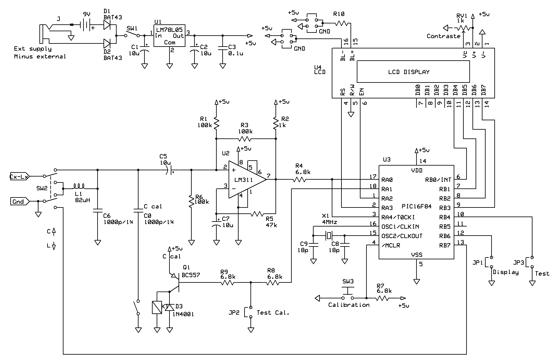
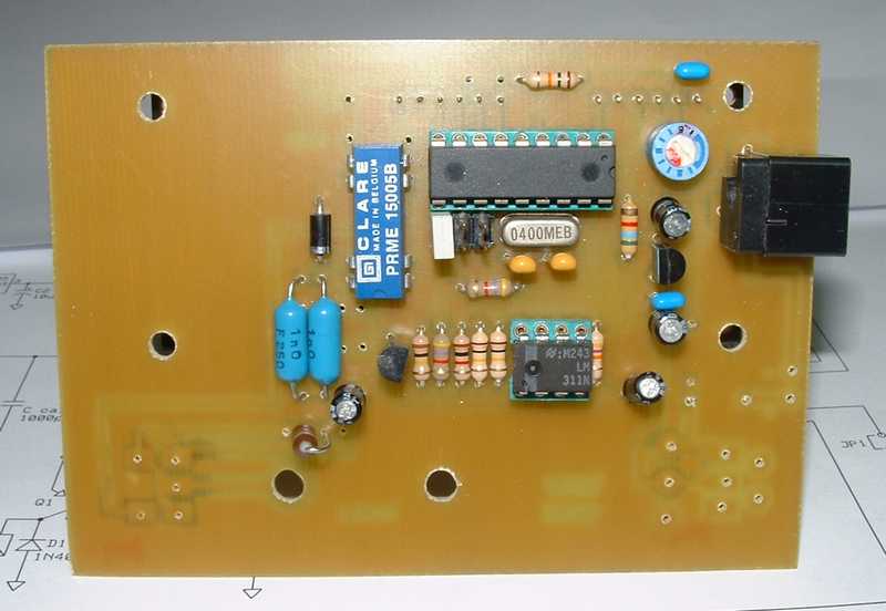
The circuit is built around a PIC 16F84A microcontroler, or its replacement 16F628A. The oscillator around a LM311 OP-amp.
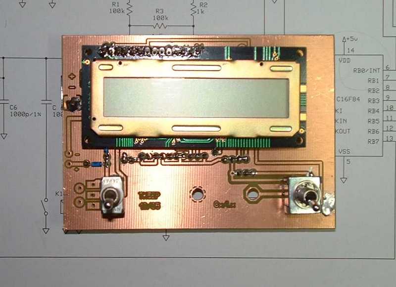
The display is a one line, 16 characters LCD ref. LM020L i had in my junkbox. But the software can drive 2 lines LCD as well.
The precision 1000pF capacitor is switched with help of a Reed relay.
The circuit is powered by a 9V battery or an external power source supplying a small LM78L05 5V regulator. I used a power connector which is switching the external contact on which i put the (-) line of the supply. The (+) is connected to the central lead.
The SW3 pushbutton named "Calibration" is not necessary, it is provided for resetting the microcontroler. Resetting can also be done in switching the circuit OFF and ON again.
JP1 "Display" tells the sofware to change the display data on the LCD.
JP2 "Test Cal." forces the switching of the calibration capacitor during the calibration procedure or debugging process.
JP3 "Test" puts the circuit in test mode.
The printed board and diagram have been made with help of the freeware ExpressPCB:
Download the diagram lcmeter.sch in ExpressPCB format.
Download the printed board lcmeter.pcb in ExpressPCB format.
Dwnload the diagram file in Proteus format (provideed by F1BHY)
Download the pcb file in Proteus format (provided by F1BHY)
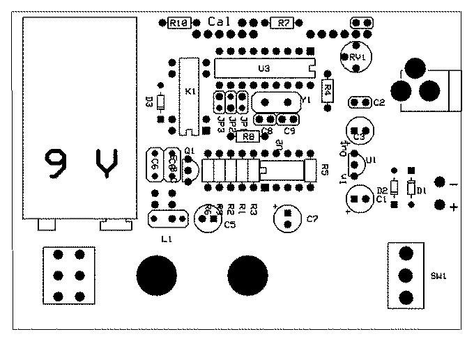
Component layout
Software :
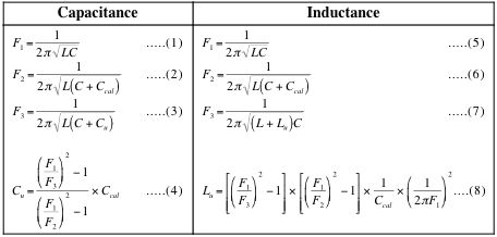
The software is written in assembler and fits in the small internal memory of the PIC. During the calibration which happens each time the circuit is switched on, the software measures the oscillator frequency F1 which uses only the internal capacitor and inductor, then it adds the 1000pF precision capacitor and measures the frequency F2 again.
Once calibrated, the software alternatively measures the frequency with only the internal components and with the unknow component (F3).
The formulas (4) and (8) are solved at each cycle to calculate the unknown component, this value is then displayed.
There are several software versions, from the original one to the latest version. They can all be found on the author's page. I personaly use the one modified by Andreas Winter who added some interesting functions and which is available here on my page.
The software allows to use different LCD displays, the JP1 jumper corrects some display anomalies.
Formulas used in the software
Construction :
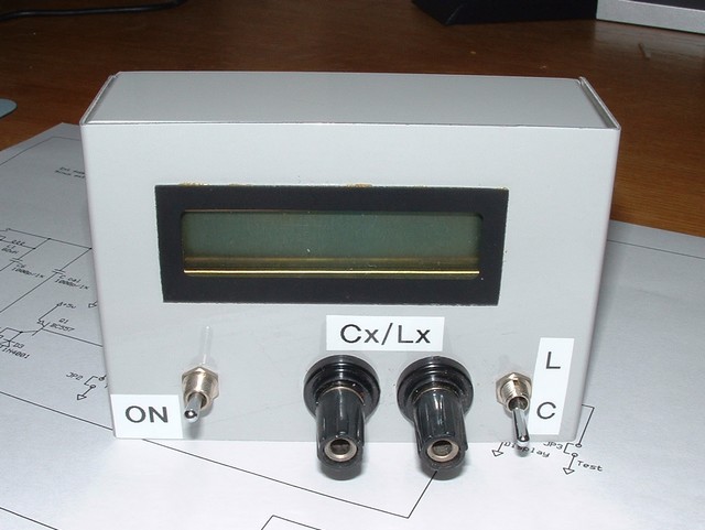
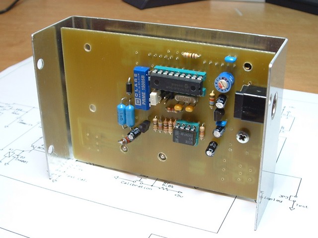
The printed board has been made to fit in a RETEX MINIBOX RM.04 case which is 105x35x55 mm large and widely available in Europe. There are no connecting wires, except the battery leads. There is only a small strapp on the +5V line.
To obtain a good precision, use a high quality capacitor for C6. A Styroflex type is quite good and stable. The Ccal 1000pF capacitor must have the best precision possible, 1% is a minimum if you want to get a good precision from your instrument.
The LCD display, a LM020L model, is mounted on the copper side of the board.
The holes and connector on the board have been made for this display. If you use a different type of display, you will certainly need to connect it with the help of small wires and change the mounting.
If the display has a backlight, the 4 solder strapps are allowing all supply possibilities. The backlight polarity and voltage is different from type to type of LCD display. The value of resistor R10 has to be adjusted to limit the current in the diode(s). You must read your LCD datasheet to know the characteristics of the backlight.
The ON/OFF and SW2 switches are soldered on the copper side and are directly screwed on the case top, they solidarize the board in the case.
Startup and use :
The 9V battery is located between the board and the case bottom.
Depending of your switches pin length, you may need to shorten them a bit, so the display is just to level with the case..
The measure terminals are directly soldered on the board, some type of terminals are too short and must be connected to the board with wires.
For debugging commodity, i suggest to use sockets for U1 et U2.
Startup and use :
Once you have finished and visually checked the board, do not insert the integrated circuits. Check the +5V voltage on pin 8 of U1 and 14 of U2. If no +5V is present, check everything until you have these supply voltages.
Insert or solder U1 and U2, put a jumper on JP2 "Test" who does switch the circuit in frequency counter mode and inverter SW2 in capacimeter position. Switch the circuit ON.
If everything is correct, the display will show something close to 0005500 which means 550 KHz.
If the LCD displays nothing or black rectangles, turn RV1 to adjust the contrast of the display.
If the LCD displays only the half of the line, insert or remove jumper JP3 and switch ON the board again.
Then place a jumper on JP2 "Test cal." who adds the 1000 pF calibration capacitor and the frequency will drop to around 0039400 or 394 KHz.
If you are so far, then your instrument is working ! Remove JP1 and JP2 and switch the circuit ON again.
Using the LCmeter is fairly simple :
In capacimeter mode, there is nothing to do after a power ON and during the calibration phase. The LCD displays a blinking C:calibrating during a few seconds and then C = 0.0 pF.
In inductance meter mode, after power ON, L:Calibrating blinks as long as you have not short circuited the terminals. This will calibrate the instrument. Then 0.0 uH should be displayed as long as you leave the short circuit and L = *???* if nothing is connected on the terminals.
Once calibrated, you only need to connect the unknow component and read his value.
Note that you can calibrate the instrument with a component connected to the terminals. This will tare the circuit with the value of your component. It can be very helpful when you want to compare several components of same value. Remove the component and replace it with another one and the DIFFERENCE between both will be displayed.
For your information, the circuit sucks 15 mA in normal use.
Précision :
The precision of the LCmeter depends mostly of the precision of the calibrating capacitor. The minimum tolerance for this 1000pF capacitor is 1% if you want a good instrument. The more precise the calibration capacitor, the more precise your LCmeter will be.
The nature of the inductance L1 of 82uH influences the precision also. A moulded coil gives a 1% precision. Certain ferrite wounded coils are giving variable results depending of nature of component to measure.
The are no linearity problems, the circuit has the same precision over the whole range.
Conclusion :
You are now the owner of a cheap, precise LCmeter which will help you finding the right value of a capacitor or a coil. You can now use all these unknown components you kept all these years !
In case of problem, feel free to contact me and i would be happy to help.
I would like to thank Phil VK3BHR for his description and free software.
The diagaram and board have been made with the free software EXPRESSpcb available on this site.