")
")
 |
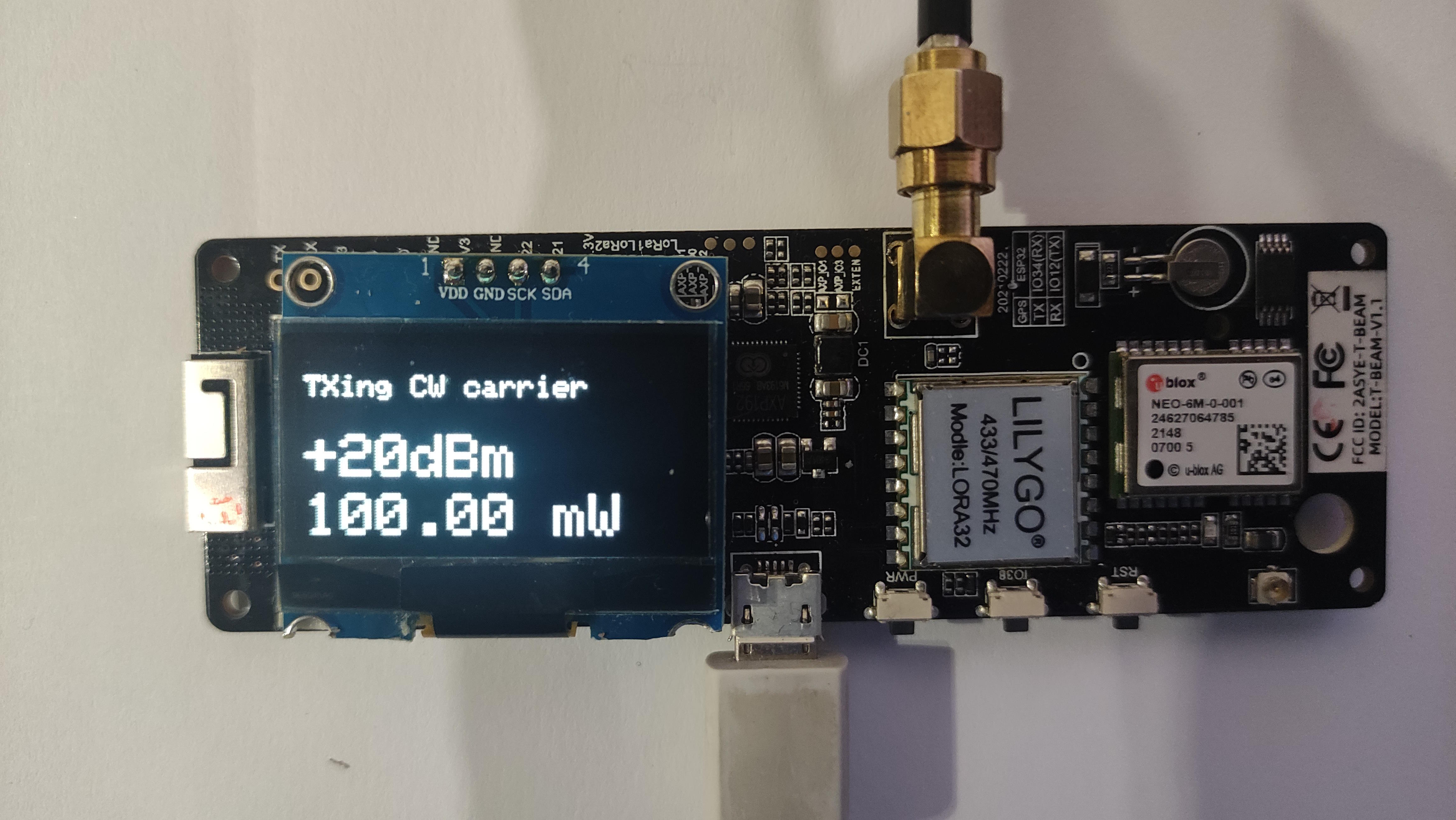
Lilygo LoRa modules from Lilygo are advertised to provide a power output of +20dBm (100mW). I found that none of my modules reached the advertised power, which was more like +17dBm. |
Transmitter test software
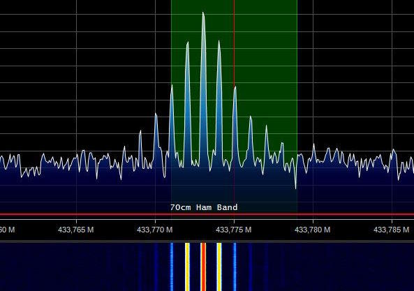
The software is designed to produce a cyclically and continuously modulated FM signal on 433.775 MHz (configurable).
The main loop produces several successive power levels (number and levels configurable) of configurable duration.
At each power level, the modulation frequency increases by a programmable step (100Hz by default), enabling the process to be better understood by listening to the signal produced on a receiver.
For example, a sequence might be: 5s at +2dBm modulated at 1000Hz, then 5s at +10dBm at 1100Hz, then 5s at +20dBm at 1200Hz, etc...
Once the last level has been reached, the loop starts again at the 1st level, and so on.
This makes it easy to measure power and frequency.
On my modules, I only reached +17.1dBm on the best of them. Frequency is rarely perfectly tuned and stable.
The OLED display shows all phases of initialization and program running. The same detailed information is available on the 115200 baud serial port (default).
The lines to be modified in the script to suit your needs are :
// If LilyGo T-beam board. Comment out for this board//#define Lilygo_tbeam// If LilyGo T3 board. Comment out for this board#define Lilygo_T3// defines the OLED driver type comment out if using SSD1306 driver. Comment if 1.3" inch uses SH11106#define ssd1306// TX delay in ms at each powerint TXdelay = 2000;// TX frequency in MHzdouble TXfreq = 433.775;// audio start frequency in Hzint TXtonebase = 1000;// audio step in Hzint TXtonestep = 100;// array in which all desired power levels are given in dBmconst int PowerArray [] = {2,4,6,8,10,17,20};
The upper configuration produces a signal on 433.775MHz at power levels +2,+4,+6,+8,+10,+17,+20 dBm durint 2s à each step and modulated at 1000Hz increasing 100Hz at each step.
The module used is a LilyGo T3 with a OLED driver SSD1306.
Receiver test software
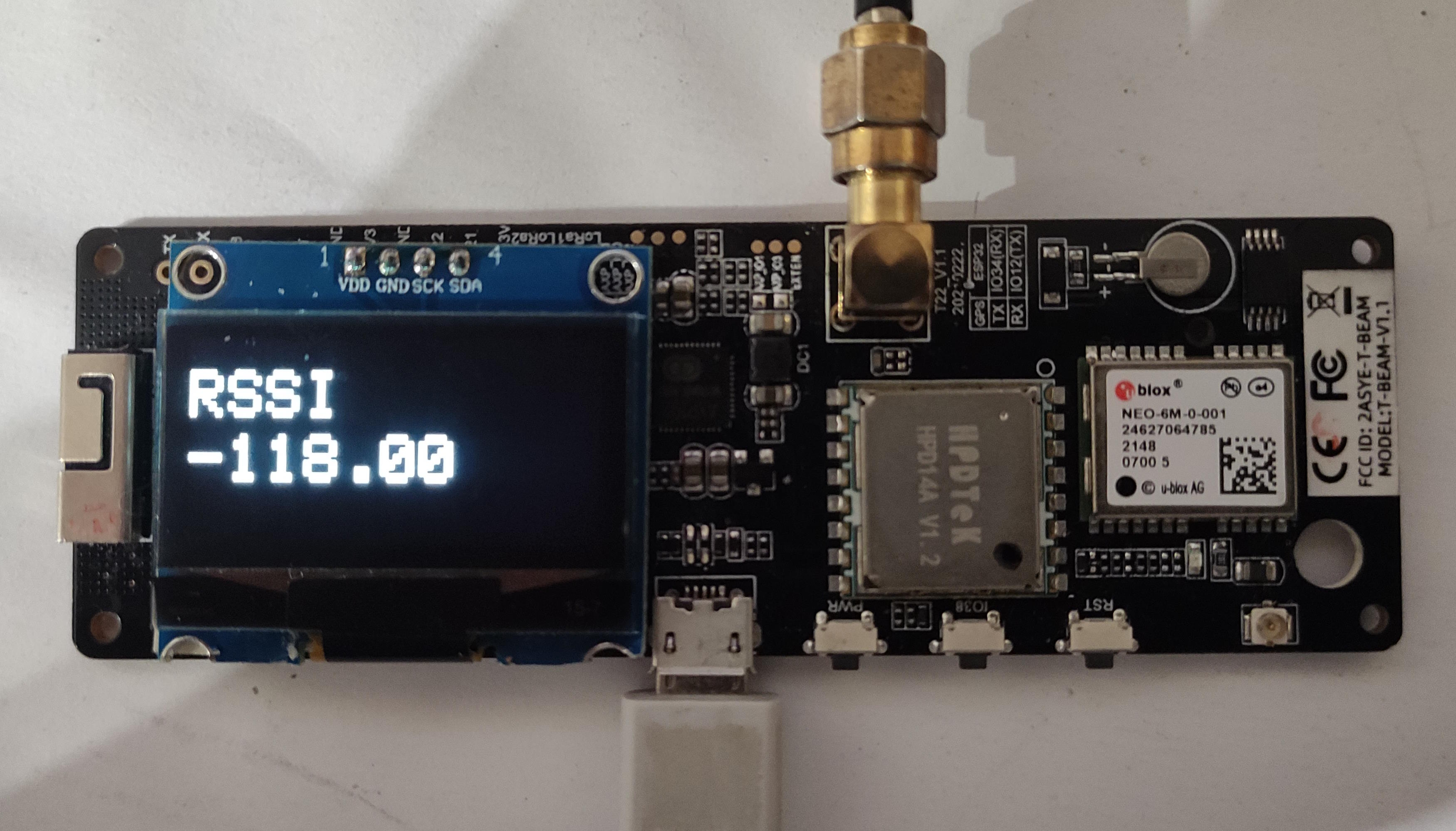
The script switches the module to FSK reception and continuously displays the RSSI level on the OLED screen and transmits it to the serial port at 115200 baud (default).
Sensitivity can then be measured by injecting a signal of known level using a generator and comparing it with the level displayed.
The level without signal is, on my modules, about -118 dBm.
There's very little to set, just the type of module, the type of screen driver and the frequency.
#define Lilygo_Tbeam//#define Lilygo_T3//#define ssd1306double RXfreq = 433.775;
The software was tested with Lilygo T3 and Tbeam modules.
The software was written under PlatformIO and is available on my Github site.