")
")
 |
Description of a versatile weather station. Features : - Built around a TTGO T3 LoRa 433 MHz module - Sensors for temperature, pressure, humidity, rainfall, wind speed and direction. - Protocols: APRS via LoRa, APRS-IS, MQTT and Wunderground via WiFi. - Wifi with DHCP or static address - OLED display with or without screensaver. - Password-protected OTA updates. - Web server with all datas. - LoRa fallback if WiFi or Internet fails - etc... |
Overview :
The weather station described here uses a TTGO v3 1.6.2 module and various sensors. It displays the data on an OLED screen and transmits them among a choice of protocols to the APRS, APRS-IS, Wunderground servers or via an MQTT broker.
APRS data is transmitted on 433.775 MHz (can be changed) using the LoRa protocol.
APRS beacons picked up by iGate gateways are then transmitted to APRS servers.
In APRS-IS, MQTT and Wunderground, data is transmitted via a WiFi connection. The connection can be made via DHCP or static address.
A BME280 or SHT31 sensor measures temperature, humidity and barometric pressure(BME280 only).
An anemometer and wind vane are collecting wind values using the ModBus RS485 protocol.
A MISOL (or other trade) bucket rain gauge measures the rainfall.
The software is currently used by stations in France, Italy, the Czech Republic, Germany, Chile, Sweden and Belgium.
Software :
The software has been written for the PlatformIO development platform.
However, the software can also be compiled using the Arduino IDE.
During my tests with pulse-sending sensors, it turned out that the ESP32's interrupt handling is faulty and contains a serious bug. For example, when you only want to count rising edges, the counter counts both rising AND falling edges.
So I looked for another solution, and was interested in RS485 wind sensors, which are at the same price as pulse or voltage sensors. So I chosed this solution.
![]() At the moment, the rain gauge is still using ESP32 interrupts, so there may be some errors in the measurement. I'm going to look into another counting method.
At the moment, the rain gauge is still using ESP32 interrupts, so there may be some errors in the measurement. I'm going to look into another counting method.
The libraries used are standard, except for the one managing wind sensors using the ModBus RS485 protocol, which I wrote myself for the wind sensor models used here.
Principle of operation:
The heart of the station is a TTGO T3 module comprising :
- ESP32 microcontroller
- a 0.96-inch OLED display
- a 433 MHz LoRa transmitter/receiver
- a WiFi interface
- a Bluetooth interface (not used in this project)
The software can be used to configure one or more of the following sensors:
- BME280 or SHT31 for temperature, humidity and atmospheric pressure (BME280 only)
- bucket rain gauge
- wind vane and anemometer with ModBus format and RS485 interface.
It also allows the data collected to be transmitted at regular intervals to one or more destinations and modes:
- the APRS network via UHF LoRa transmission
- the APRS-IS network via WiFi access
- a WiFi MQTT server
- the Wunderground weather station network via Internet WiFi
A "settings_sample.h" configuration file is read at startup, containing all the above configuration information and choices.
One can use as many setting files, in changing their name and modyfing the include line in the main program. This is usefull if there are different stations in use.
Rain and wind data are measured every second to produce sliding averages over 2min, 10min and 1h, depending on the sensor.
Temperature, humidity and pressure data are read just before transmitting the datas. By default, data are transmitted every 2 min (TXPERIOD).
The Web page is updated every 10s
The windvane's direction is displayed on a sliding average to avoid too many changes of direction due to wind instability..
Hardware :
- TTGO T3 module
- RS485 interface
- DC/DC converter 5V
- BME280 sensor
- SHT31
- RS485 wind speed and direction sensors
- rain gauge
- a 12V power supply
The various modules interconnect as follows on the TTGO module:
- BME280 or SHT31 on i2c port: SDA pin IO21, SCL pin IO22
- RS485 interface: RxD IO34, Txd IO04
- Rain gauge IO14
- ModBus address setting switch on pin IO25
(see interconnection diagram)![]() The RS485 sensor cables can have different colors. The A+ wire can be YELLOW and not GREEN.
The RS485 sensor cables can have different colors. The A+ wire can be YELLOW and not GREEN.
The RS485 bus is connected to the RS485 interface board on pins A, B and Ground.
The wind vane and anemometer must be supplied with a voltage of 10 to 30V. 12V works perfectly in my case.
If the distance between the Arduino and the sensor exceeds a few meters, you'll need to connect a 120 Ohm terminating resistor at the sensor end of the bus.
Construction:
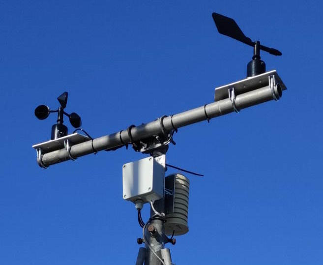
The assembly is mounted at the top of a tube, which is placed in an open area that should never be in the shade and with no obstacles that could deflect, slow down or speed up the wind.
I wired the various modules on a prototype board with holes. The modules are plugged into pin headers so that they can be replaced relatively easily.
My first attempt ended with a failure, the station lasted a week before being stopping to report all BME280 datas. A lot of connections we completely oxidised.
It has to be said that the weather was particularly bad during that week, with several days of strong winds at times > 120 km/h and driving rain that sometimes fell horizontally, all at an altitude of 780 m !)
My first casing wasn't sufficiently waterproof, so you need at least IP67 protection.
Update 12/12/2023 - New plastic box that I've tested for perfect waterproofing. (IP67)
I also protected all the modules and connections by applying varnish.
The wires are routed through cable glands.
I've put the BME280 into a tube of pills in which I made openings to let the air circulate. The openings are covered with a piece of dishwashing scouring pad. This "should" let the air pass through, stops the insects and not retain too much humidity.
But from previous experience with my beehive reporting system, I know that the BME280 is not lasting very long in outdoor conditions.
The SHT31 sensor MIGHT Be better as it has a Teflon filter.
The diagram and following picture will give you an idea of the assembly.


Jérôme F4FEB designed and produced supports for the wind and rain sensors to be printed with a 3D printer.
The diameter of the tubing support is 40mm.
You can download the result of his work here.
I don't have a 3D printer myself, so I wasn't able to test this support.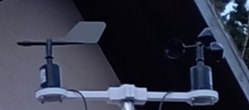
Software :
The software was written in Visual Studio Code (VSC) and PlatformIO, which has become my favorite editor/compiler.
The libraries required are :
- Wire, WiFi
- Adafruit GFX, SSD1306, Sensor and BME280
- Rob Tillart SHT31
- LoRa by Sandeep Mistry
- PubSubClient for MQTT by Nick O'Leary
- ElegantOTA
- AsyncTCP and SyncWeberver
- wind_rs485 by myself
Only the "settings_sample.h" configuration file needs to be modified as required.
The first time, compile and transfer the software via the serial port to which the module is connected..
Subsequent updates can be carried out over WiFi using OTA (On The Air).
At start-up, you need to note the IP address assigned to the module on the OLED screen or transmitted via the serial port, and then open a browser page at this address: xx.xx.xx.xx/update.
Then transfer the file: /.pio/build/tgo-lora32-v21/firmware.bin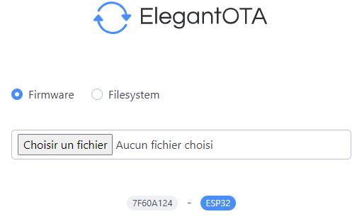
The software and all documentation is available on my Github, or on request.
Configuration :
The settings.h configuration file provides sufficient commentary to understand the purpose of all the parameters.
In the event of a problem, or to understand how the software works, you can use different levels of debugging by displaying the serial port and uncommenting one or more options at the beginning of the file: #define DEBUG_WIND for example.
By default, the serial port is configured for a 115200 Baud rate.
The Wunderground network requires you to create an account (free of charge).
Use of APRS IS (Internet Service) gateways requires a password available online, depending on the callsign used : https://apps.magicbug.co.uk/passcode/
Uploading to an MQTT server requires the creation of topics. Examples are given in settings.h
It is not advisable to validate APRS and APRS-IS at the same time, as APRS servers may not appreciate !
The RS485 wind sensors are all supplied with the same default address: 0x01.
On the ModBus bus, however, each sensor must have its own address. By default, the settings.h file assigns address 0x01 to the anemometer (AddressSpeedSensor) and 0x02 to the wind vane (AddressDirSensor).
It is therefore necessary to change the wind vane address to 0x02. This value is defined by the NewSensorAddress parameter in the configuration file.
This can be done using the configuration software supplied by the manufacturer via an RS485 interface on a computer serial port, or using my weather station software.
Connect ONLY the wind vane to the bus and connect pin IO25 of the module to 3V3. The green LED should light up.
Press the RESET button to reboot. If all goes well, the address should have been changed and confirmed on the OLED display.
Switch off the wind vane power supply and remove the 3V3 connection to pin IO25. Connect the 2 sensors and reboot.
Usage :
Once configured, operation of the software requires no special comment.
Once started, it is autonomous and, after all sensors have been measured, it transmits immediately on start-up.
Subsequent transmissions will take place cyclically after the TXPERIOD parameter delay. (default 120s).
At start-up, the first screens are displaying the modes used as well as the IP address that has to be noted to access to the Web page.
If there is a communication fault with the wind sensors, a small logo appears in the top right-hand corner of the OLED.
The OLED display shows most informations, and in real time.
Information are also is available on the USB port at a speed of 115200 Bauds, depending on the debugging level selected in the configuration file.
If the screen saver is not active, the display will remain permanently lit.
If it is activated with parameter ECOMODE = 1, it will switch off completely after the 1st beacon has been sent, allowing you to check that the system is operating correctly beforehand.
If ECOMODE=2, it will switch off as above and light up during 5s during data transmission.
A web page is available at the module's IP address: http://xx.xx.xx.xx
It displays all measurements, some settings and the uptime. (running time since last boot)


As with any radio installation, to get good performance, you need to take care of the antenna.
The small "rubber duck" antenna supplied with TTGO modules has poor efficiency and MUST be replaced if good performance is to be achieved!
The test weather station has been in operation since 11/23/23 at the Punta site in JN41IW at 780m asl, with callsign TK5KP-13.
Public data can be viewed on aprs.fi and Wunderground.
Feedback :
12/12/2023 : The BME280 sensor was no longer responding. Totally oxidized.
New test with the probe enclosed in a tube of pills in which I made openings to let air circulate and a protection with a piece of dish scraper pad.The air passes through well and it should withstand the weather, not hold too much moisture and filter out insects and dust.
12/03/2024 : Replaced the anemometer, which hadn't been responding for a few weeks. When I dismantled it, I noticed that there was a lot of water in the sensor!
The new anemometer turned much less easily than the old one, probably a problem with the quality of these sensors.
I therefore interchanged the upper part of the 2 sensors and protected the junction between the 2 parts of the casing with adhesive tape.
Tighten the 3 housing assembly screws. Mine were badly tightened, which may explain the watertightness problem. Or is the water coming in through the anemometer shaft?
13/12/2024 : Due to repeated failures of the BME280 sensor, which sends 100% humidity after a few weeks or months, I now use the SHT31, which has a reputation for being less sensitive to sustained high humidity.
With the loss of pressure measurement.
Links :