")
")
My previous 10 MHz frequency reference having broken down, the question was whether to repair it or move on.
After reflection, I decided to equip myself with a 10 MHz reference disciplined by GPS (GPSDO) in order to obtain the best possible accuracy.
After some research on the Internet, I found ready-made products at affordable prices and some descriptions of amateur achievements.
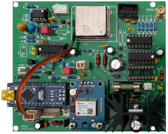
I chose the option of making the version proposed by DL4ZAO / DL7UKM . On one hand because there is a detailed description (in German) and that the author offered the printed circuit at a correct price, and on the other hand to learn according to the formula " Build and learn ".
The assembly revolves around an Arduino Nano and software is offered by Michael DL7UKM. All the more reason for my choice, now having a good knowledge of this platform.
Operating principle:
The assembly comprises:
- A 10 MHz OCXO
- A GPS receiver
- A chain of dividers
- A phase comparator (PLL)
- A DAC converter (digital / analog converter)
- A micro-controller
- An LCD display
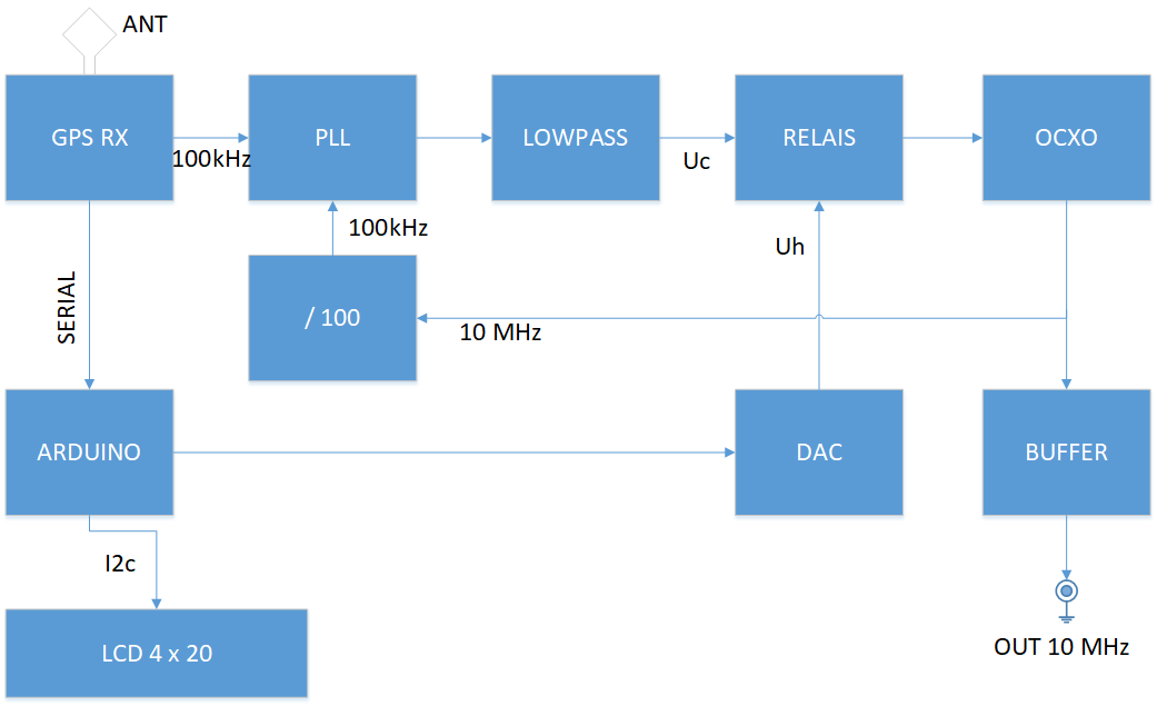
OCXO already has excellent stability due to its internal temperature stabilization. This stability and accuracy is enhanced by the PLL which compares the divided 10 MHz output with the GPS clock output and sends a correction voltage to the OCXO.
If the GPS reception disappears, a relay switches and applies to the OCXO the voltage coming from the DAC which is equivalent to that coming from the comparator in order to continue to obtain the best precision.
The microcontroller controls all the editing and makes the necessary decisions and displays the information on the screen.
Before purchasing the components, it is necessary to determine the desired clock frequency at the output of the GPS.
The choice is to be made according to a compromise between speed of synchronization, short and long term stability.
1kHz provides better long-term stability but takes much longer to synchronize. Conversely, 100 kHz synchronizes faster at the cost of a slight loss of stability which remains excellent and WIDELY sufficient!
My choice fell on 100 kHz, I planned to use the assembly only once in a while and did not want to leave it powered on all the time. This choice is the only one to configure in my software.
Once the components were assembled and the assembly completed, I loaded the software into the Arduino Nano.
The edit worked the first time and after receiving 4 satellites, the edit indicated that it had synchronized.
After having exchanged many times with the authors in order to understand the operation of the editing and the software, I wanted to make my own software by taking the parts that suited me and writing those that I wanted. The original software having certain shortcomings to my taste ...
In the end, my software allows new functionalities and automation of certain functions which require manual adjustment with the original software.
Software operation
The functionalities are as follows:
- Normal, Holdover and Forced Holdover operating modes.
- Adaptive determination of nominal control voltage in HOLD mode.
- Saving parameters in the Arduino's EEProm.
- Possibility of using a temperature probe.
- Two main data display screens on a 4-line LCD display.
- Synchronization state display LED.
- Backlight ON/OFF controlled by pushbutton
At startup, the software checks whether data has already been stored in EEPROM. If not, it assigns the default value of 2.500 V to the DAC.
The software checks at each loop (set at 1s), if the PLL is locked, the number of satellites received, and the state of geolocation.
If these 3 conditions are met, the LOCKED state is validated.
The relay then switches to the LOCKED position and applies the output voltage of the PLL comparator to the control input of the OCXO.
The locking loop is then established and after a certain time stabilizes when the OCXO has reached maximum temperature and stability.
If all the conditions for locking are not met, the relay is put in the HOLD position and the input of the OCXO is applied to the output voltage of the DAC (which in the end, once the software has done its work, is identical at the loop stabilization voltage).
Every 10 minutes, the software compares the voltage applied to the OCXO with that measured 10 minutes earlier.
If the 2 voltages are identical, a flag is incremented.
At the end of 30 minutes (flag at 3), it is estimated that the locking loop is stabilized and the software then compares the output voltage of the DAC with that applied to the OCXO. If it is different, it adapts the value of the DAC so that the voltages are identical and the saving in EEPROM for the next start.
Otherwise, the flag is reset, and the process starts over. This principle is the same each time you switch to HOLD mode. (satellite loss, M / A, etc ...)
For test or any other reason, you can force the application of the DAC output to the OCXO. This is the FORCED HOLD MODE, accessible after a long press on the button.
The control LED has three states:
- Fixed state = LOCKED mode
- Slow flashing = HOLD mode, or LOCKED mode of less than 10 min
- rapid flashing = FORCED HOLD OVER mode
I used the standard Arduino libraries excluding:
NMEAGPS.h for managing Ublox GPS modules (NEO6, 7, 8)
avdweb_Switch.h for managing the push button
use
It is necessary to configure the GPSDO_settings.h file if you want the maximum precision in the display of the voltages, you must measure the 5V supply voltage applied to the Arduino Nano on the 5V pin and enter this value in the GPSDO_settings.h file and recompile the sketch. This is however optional!
This file also sets the speed of the serial port, by default 115200 Bauds and the output frequency of the GPS, by default 100 kHz.
It is then of course necessary to recompile the sketch.
At start-up, the display shows the software version and the DAC value stored in EEprom.
A push button allows:
- By long press to switch to FORCED HOLD MODE
- By short press to change display.
- By double pressing to turn on or off the backlight
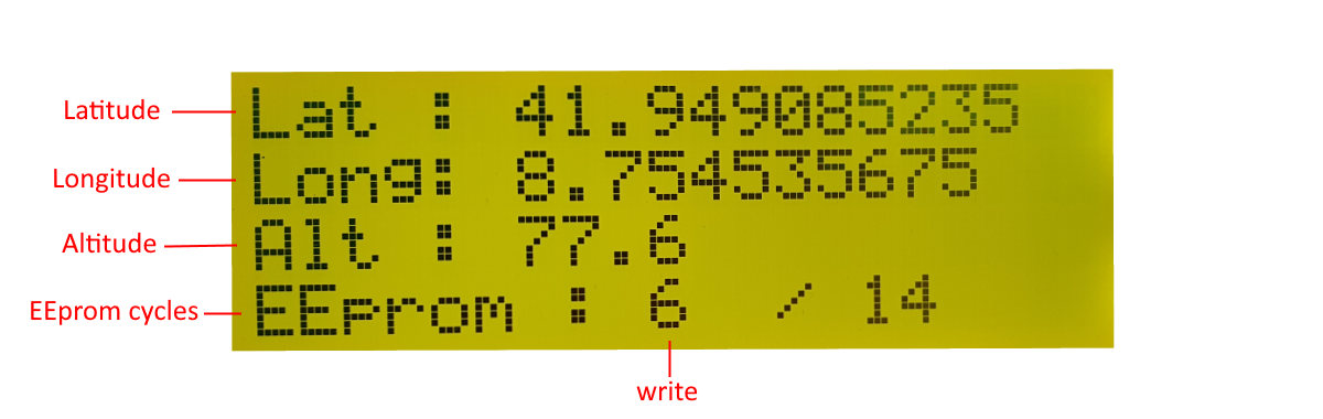
In normal operation, the LCD screen displays the following information:
After pressing the push-button, a second screen displays the following information:
The software can of course be modified to display what you want, but it is then necessary to modify the displayInfo () or displayLatLong () functions in the sketch and recompile it.
After a few minutes of operation, a sufficient number of satellites must have been acquired and the geolocation made.
The screen should then show the time and the QRA locator and lock indicators show LL.
As the operating time of the assembly progresses, the voltage noted Uc must stabilize around a certain value proving that the OCXO has reached its normal operating temperature and that the loop is stabilized.
30 min later at most, the voltage Uh must be equal or very close to Uc. The assembly is then stabilized and the value of the DAC for the voltage Uh is stored in EEprom for the next start-up.
The software is still evolving, please contact me to get a copy.