")
")
 |
During my SOTA activities, I often raged on the fact that the builtin CW keyer in my QRP SW-3B transceiver only had one memory ... It is indeed very practical to have several of them in order to free your hands to do something else such as finishing writing the last QSO on the logbook or making a somewhat specific call. The idea therefore sprouted to produce a CW memory manipulator that would meet the following conditions |
- 3 on the fly programmable memories
- low power consumption
- easy battery supplying
- reduced size
- easily reproducible
Having already built a prototype of the fabulous K3NG keyer, I decided to use this project by adapting it to my needs.
Study :
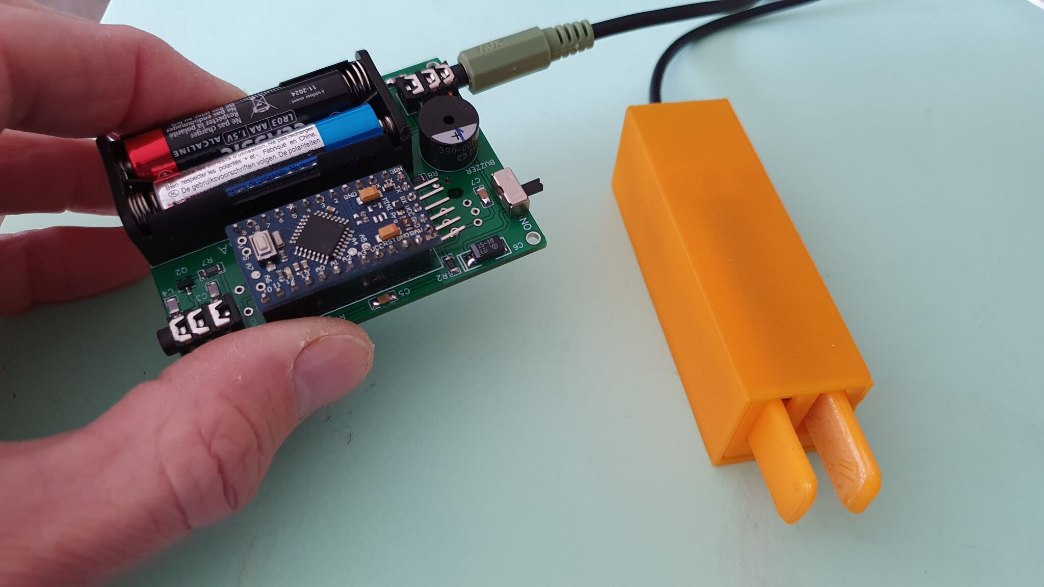
For the power supply, I chose a pair of AAA type batteries which therefore provide 3V, are quite small and on sale everywhere which is handy for a project that must be used on the go and may require an unplanned change of batteries.
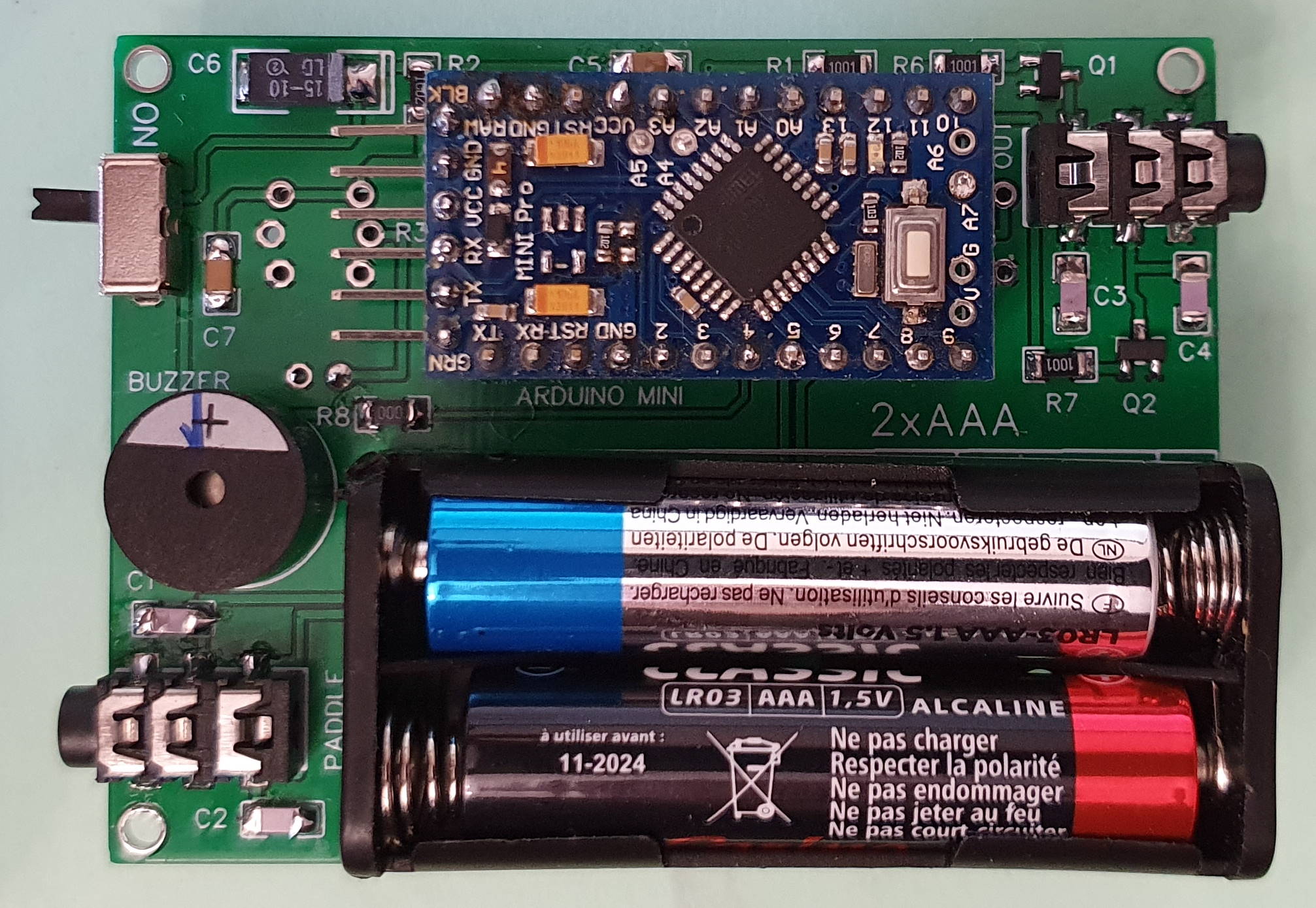
The heart of the assembly is an Arduino Mini because I had several in stock and it is easily modifiable to reduce consumption. It does not have items such as an USB port which are not useful in my project and would consume power unnecessarily. The Arduino is supplied with 3 V directly via the VCC pin.
To limit consumption, the software's SLEEP function is used, which switches the keyer to standby after a certain period of non-use. The current used is then very low, which originally made me consider not using an on / off switch, but I added one to avoid accidental button presses during transport. In operation, the manip consumes about 3.3 mA and in standby less than 1 uA!
To limit the size and weight, it was chosen not to install a speed adjustment potentiometer. The speed is modified using the paddles.
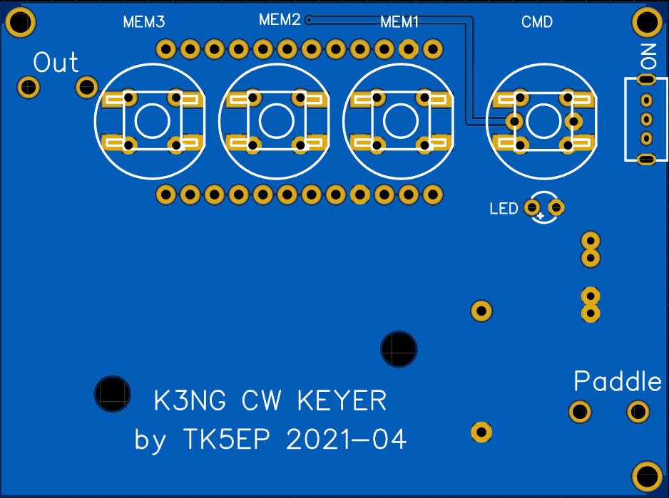
In order to facilitate the construction, I chose to use a printed circuit board with all the components including connectors, pushbuttons, switch, battery support and LEDs. The components are welded on both sides, the battery box on the underside and the + LED keys on the top.
Integration is done in a small TEKO 2 / A-1 box with dimensions of 72x57x28 mm.
Building :
In order to minimize the consumption of the Arduino Mini, it is necessary to unsolder everything that is useless, namely the voltage regulator and the power-on LED as shown below.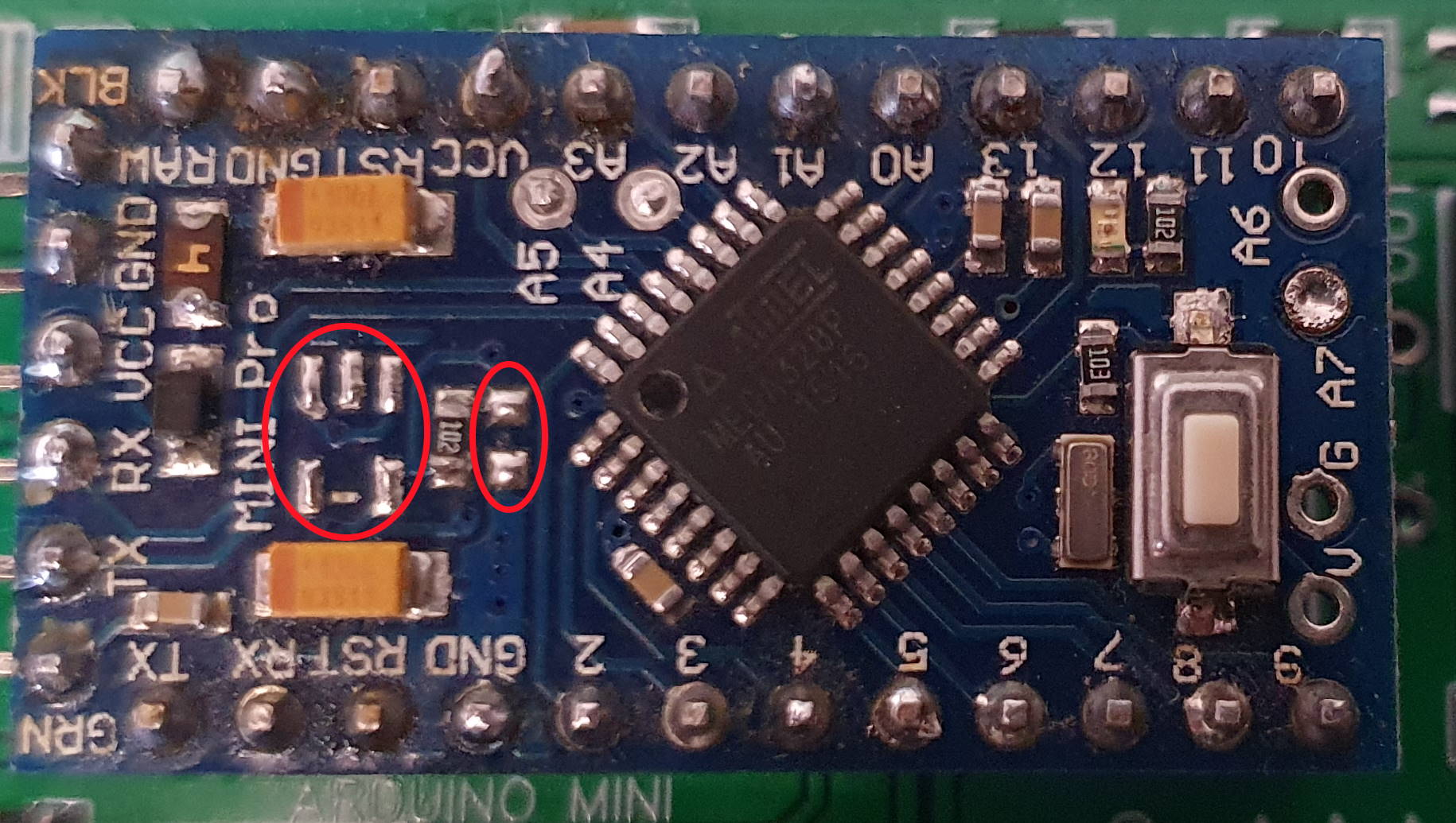
To program the Arduino, it is necessary to solder the 5 pins on the left in the image below, but UNDER the PCB in order to reduce the height of the assembly.
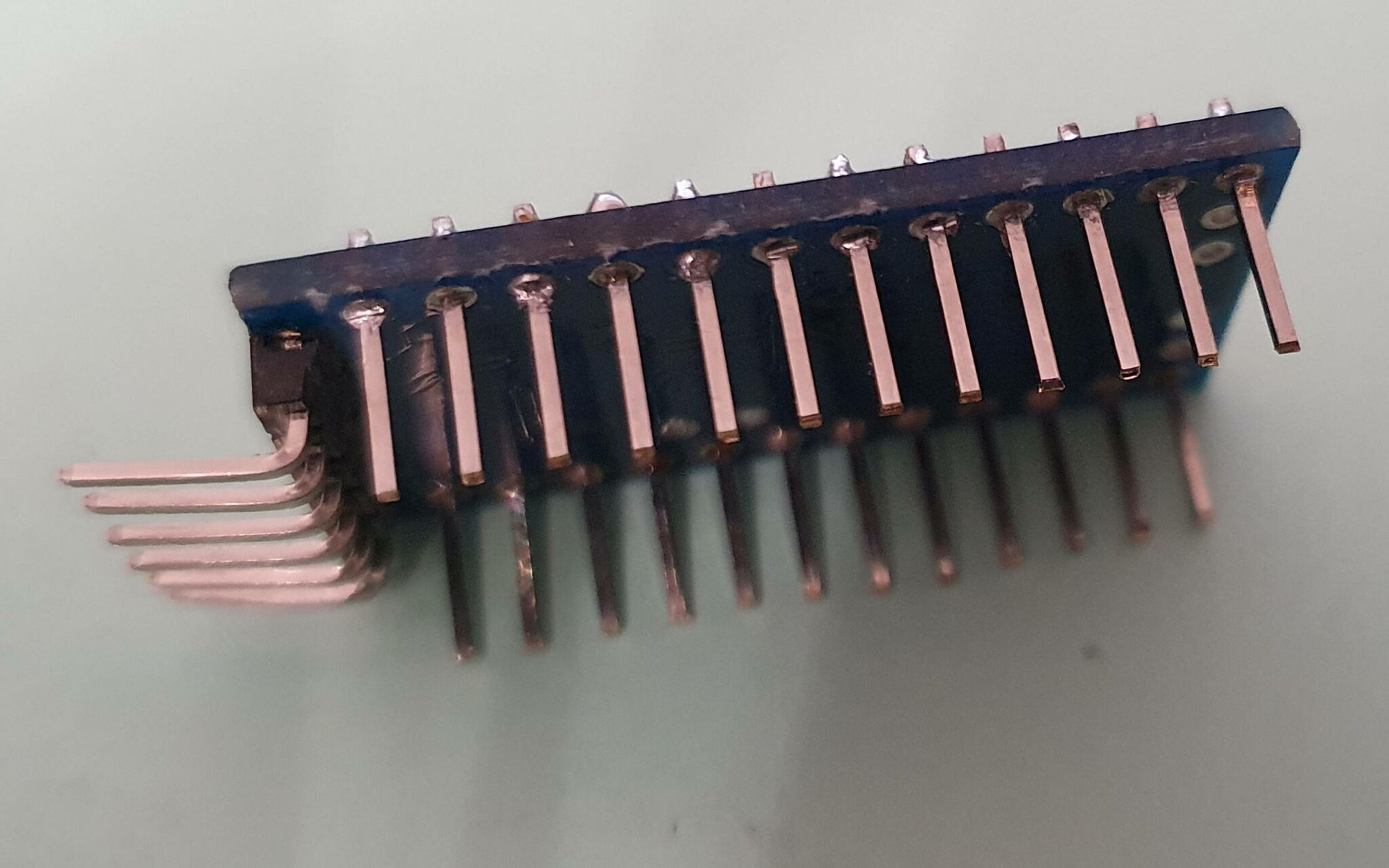
The Arduino can be soldered directly to the printed circuit with the disadvantage of then being difficult to unsolder. It is better to put it on a support.
I used female pins sold in 40 pin length and cut to 12. To gain height, the male pins will be soldered onto the Arduino without the plastic part. I first welded the bar with the plastic to make it easier to weld and then removed this plastic.
Solder all SMD components on the component side starting with resistors, capacitors, transistors, connectors, battery holder + Arduino and buzzer. The ON / OFF switch can be soldered on the top or bottom of the PCB according to your wish.
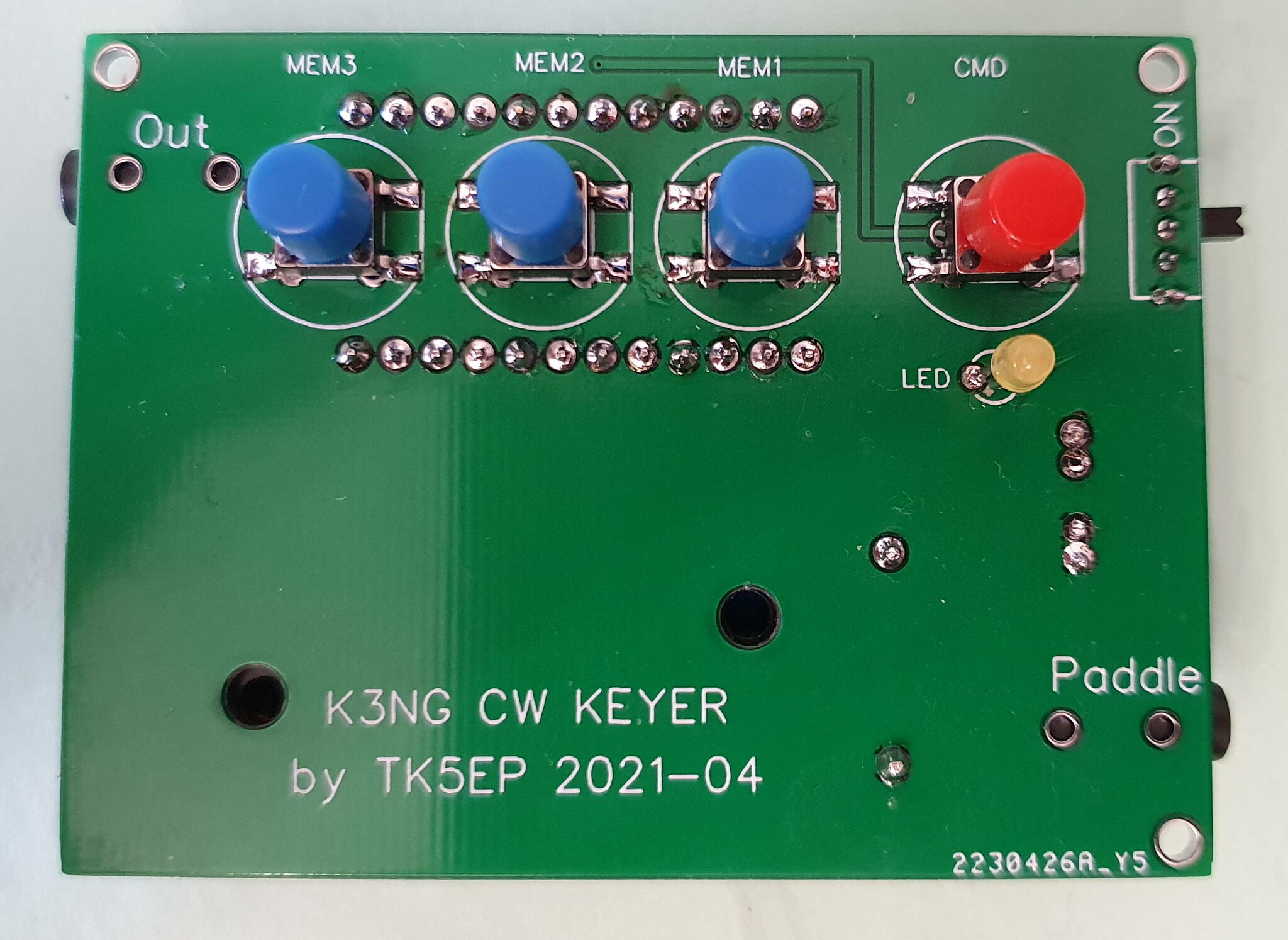
Then solder the pushbuttons and the LED on the underside of the PCB.
The layout allows the use of 2 types of keys, a model of the more expensive D6 series which allows the integration of the control LED in the key and another very inexpensive CMS model with a separate LED.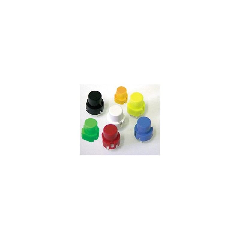
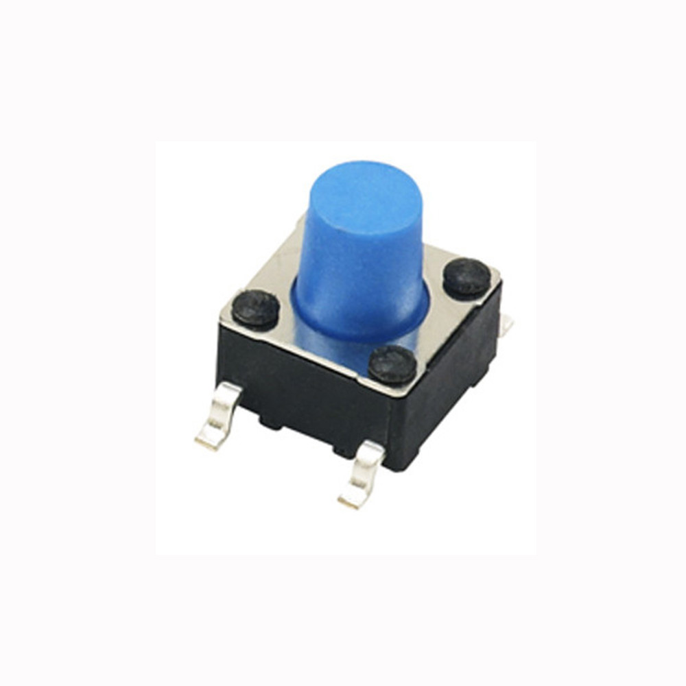
I bought small caps that fit on the keys, but you can do without if you choose keys with a sufficiently long button.
 |
 |
 |
 |
The circuit will then be integrated into the TEKO 2 / A.1 box for which the PCB has been made.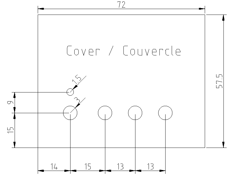
The PCB is self-supported by the 2 jacks and some foamglued on the bottom of the case.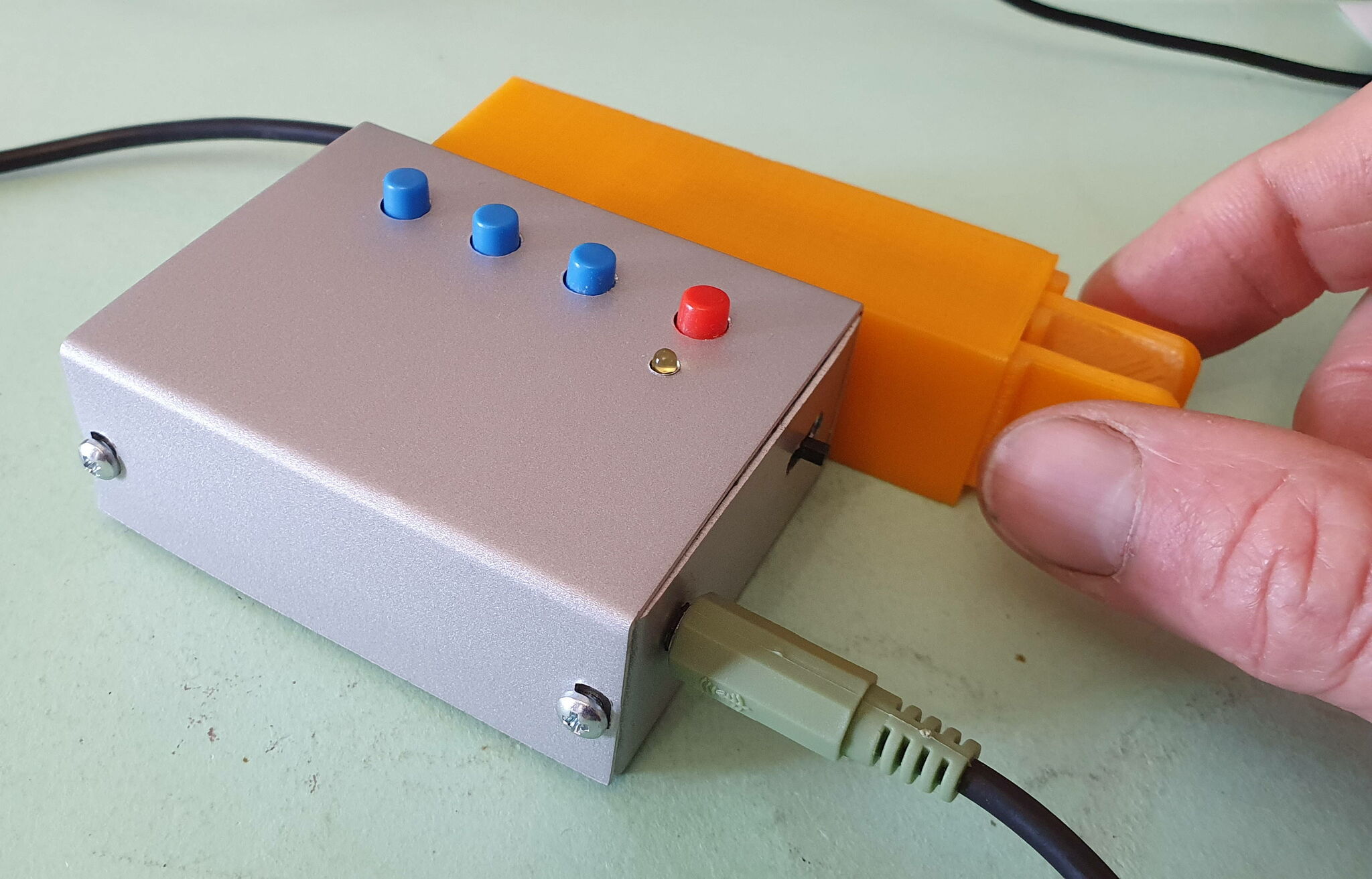
For those who would be interested, I have some printed boards that I can give away with the on / off switch and the 4 pushbuttons.
Software :
In order to "fit" in an Arduino Mini, the software is calibrated with a limited number of functions. Exit all that is useless ...
Below are the parameters to modify in the configuration files.
File Keyer_features_and_options (only this lines were uncommented)
#define FEATURE_BUTTONS
#define FEATURE_COMMAND_MODE
#define FEATURE_MEMORIES
#define FEATURE_SLEEP
#define OPTION_PROG_MEM_TRIM_TRAILING_SPACES
#define OPTION_DIT_PADDLE_NO_SEND_ON_MEM_RPT
#define FEATURE_COMMAND_MODE_ENHANCED_CMD_ACKNOWLEDGEMENT
File Keyer_settings
#define go_to_sleep_inactivity_time 1 (voir ci-dessous)
#define analog_buttons_number_of_buttons 4
File pin_settings
#define paddle_left 6
#define paddle_right 5
#define tx_key_line_1 10
#define sidetone_line 4
#define potentiometer 0
#define ptt_tx_1 11
#define analog_buttons_pin A0
#define command_mode_active_led 12
To facilitate the loading of the software, I provided the HEX format file and the folder for the Arduino IDE.
To load this file into the Arduino, you can use various methods, including the XLOADER software.
When compiling with the Arduino IDE, choose the board pro-mini and processor ATmega328p 3.3 V 8 MHz.
Version with 15s standby without wakeup by memory keys.
Version with 15s standby and alarm clock by memory keys.
Using the keyer :
The keyer goes into automatic standby after 30s (configurable). In order to avoid accidental waking up by pressing a memory button during transport and forgetting to switch off the remote, only pressing a paddle brings the remote from standby. This function can be modified by changing the code. (see the customization chapter)
To program the memories, change the parameters (speed, type of manipulation, etc.), switch to COMMAND mode by pressing the CMD key. The COMMAND mode is confirmed by a double tone from the buzzer and the lighting of the LED.
Commands are passed to the software by manipulating letters following the information below.
To exit command mode, press the CMD key again or send the letter X, the command is confirmed by a double tone inverted compared to that of the COMMAND entry.
MEMORIES
1 to 12 - play memory content
Px - program memory x (1 to 12), or press memory button after command button
Yxxxx - change memory repeat delay to xxxx ms
REPEAT : press the memory button and keep it pressed then briefly touch a paddle, release memory button.
ERASE : simply change memory but leave empty
SPEED
E - Announce speed
W - change keyer speed with LEFT (plus) and RIGHT (minus) paddles.
M - change COMMAND mode speed
Speed can also be changed without entering CMD mode. Press CMD button and use left +1 or right -1 paddle.
MONITOR (ST = SIDE TONE)
F - Change monitor frequency, use paddles for higher or lower frequency
O - toggle Monitor cycles through ST OFF, ST ON, ST PD ON (paddle only, not memories )
KEYER MODE
A - Switch to Iambic A mode
B - Switch to Iambic B mode
C - Switch to Single Paddle Mode
D - Switch to Ultimatic mode
G - Switch to Bug mode
T - Tune mode press RIGHT paddle for permanent Tune, LEFT paddle for intermittent Tune
KEYING SETTINGS
H - Set weighting and dah to dit ratio to defaults
I - TX enable / disable
J - Dah to dit ratio adjust
K - Toggle Dit and Dah Buffers on and off (Ultimatic Mode)
L - Adjust weighting
N - Toggle paddle reverse
Z - Autospace On/Off
STATUS
? sends status
1) Speed in WPM
2) Keyer Mode (A = Iambic A, B = Iambic B, G = Bug, S = Single Paddle, U = Ultimatic)
3) Weighting
4) Dah to Dit Ratio
A total RESET of the memories content and all parameters can be done in pushcing both paddles and switching the keyer ON. Stay pushed about 5 seconds. A RESET does produce a special double tone.
Customization
Sleep mode exit
To modify the exit from standby by also pressing one of the memory keys.
In the k3ng_keyer.ino file change the line:
PCMSK1 = bit(PCINT9); //Turn on pin A1 en PCMSK1 = bit(PCINT8); // Turn on pin A0
Originaly, only the right key allows you to exit standby ... Unfortunate ... For the 2 keys to be active, modify the line:
//PCMSK2 = bit(PCINT21); // Turn on pin D5
in
PCMSK2 |= 0b01100000; // Turn on pin D5 & D6
and recompile the software.
SLEEP mode delay
By default, the software only allows you to set the time before going to sleep in minutes.
The following modifications in the sketch allow this to be done in seconds:
In file keyer_settings.h
#define go_to_sleep_inactivity_time 30 // délai en secondes
In sketch k3ng_keyer.ino
if ((millis() - last_activity_time) > ((unsigned long)go_to_sleep_inactivity_time*1000)){