")
")
 After buying a second hand TS850s, i needed a remote interface to connect this wonderful transceiver to my computer.
I started to built several simple interfaces using a few transistors but it never worked with ALL softwares. So i started to study my own design using the famous MAX232 and the result is described on this page.
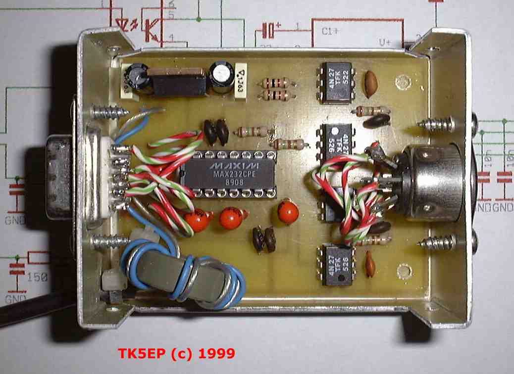
Inputs and outputs are completely insulated with help of opto-couplers preventing any "accident" happening to the transceiver. Computer and transceiver are completely insulated.
This interface works with all Kenwood transceivers which need the original Kenwood IF232 interface.
On the picture, on the bottom left part, you can see a ferrite core which is not mentioned on the diagram. In order to protect the circuit from RF fields, i wounded the power leads on this core. It is certainly not necessary, but preventing is better than curing !..
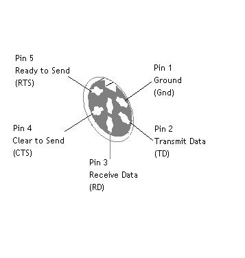
This interface is designed to be used with a 5 wire cable to the computer side, RD, TD, RTS, CTS and GND. Not every software is handling all these signals, but only the TD, TD and GND. RTS and CTS are left.
In this case, you must make a loop between RTS and CTS. This can be done by making a link on the J2 connector between pin 7 and 8. A better way is to make this link on the printed board. Doing this, you leave the pin 7 and 8 free on the connector and you can use them for another purpose.
Some logging and contest software are using the RTS and DTR signals for PTT and CW keying. So you can add 2 more wires and use these signals. The diagram gives an alternative for this solution.
On the Transceiver side, a cable connects the interface to the ACC1 connector of the TS850s. The pining on the diagram is the one of the ACC1 connector. See pining of this connector below.
Connectors pinouts
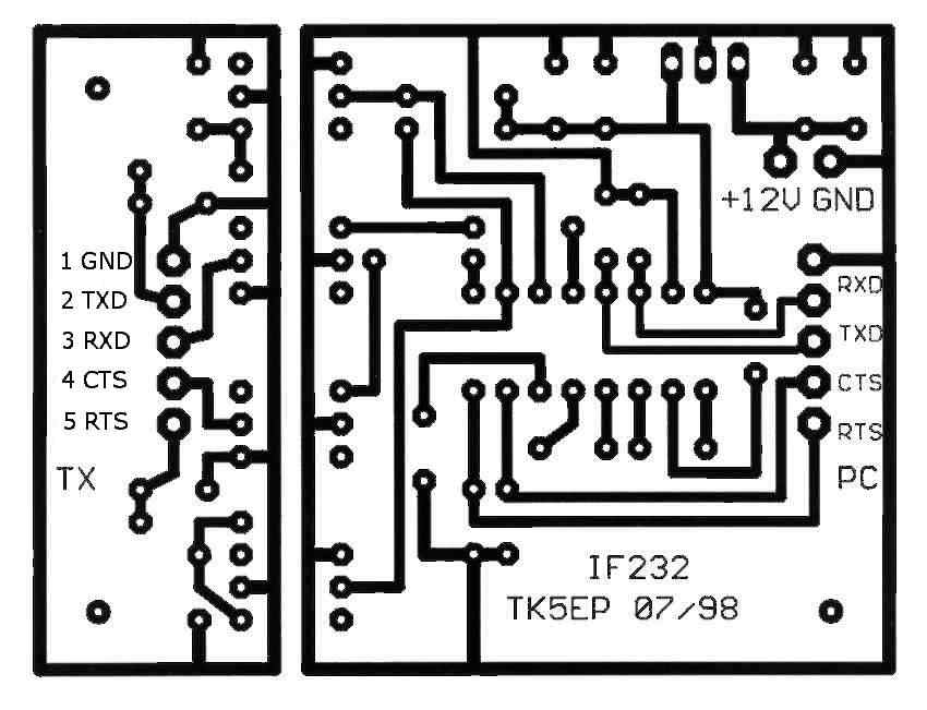
Interface diagram
Construction
The following files of the diagram and printed board have been drawn withthe free ExpressPCB software i use now and which is available on this site.
Diagram GIF format
Board in JPEG format
Layout in GIF format
Diagram ExpressPcb format
Board in ExpressPcb format
Part list
Click on the following links to get the documentations in PDF format :
MAX232 level converter (443 Kb)
4N27 opto-coupler (295 Kb)
The value of all 10uF capacitor around the MAX232 can be reduced to 1uF without any problem.
The printed board is 71x52 mm large and contained in a small case widely found in Europe, it is the 2/A.1 by TEKO, dimensions are 72x57,5x28 mm.
NOTE : the core on the picture is not on the diagram. I wounded the supply wires around it to add some RF protection.
To test the interface, you can use different softwares, i recommend you :
- BAND MASTER by VE3NEA. Very simple but suffisant to test the interface. Here is a screen copy dof the configuration.
- HAMRADIO DELUXE by HB9DRV. Complete software with DXcluster, logbook, etc...