 During our multi-multi contest operation, we came against a problem while using low band receiving antennas.
There were 3 low band stations, one on 160m, another on 80m and one on 40m.
The problem was simple : how could we share the Beverage antennas on all of these 3 stations ?
The first solution was to split each antenna in 3 directions with coaxial T's and to use a coax switch on each station, so that each station could select a different antenna. That proved to be not very satisfying, the impedance seen by the receivers and antennas were changing a lot depending on the position of the different switches.
DK4VW, Uli told me that the BCC (Bavarian Contest Club) crew was using a Beverage switching box that proved to be very efficient and i began to build such a box with his precious help.
Informations below given with permission of DK4VW.
Here the theory, only one band (160m) is represented. There are 3 identical boards :
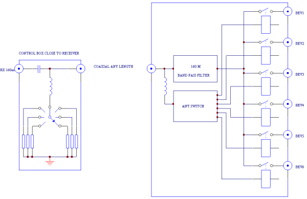
The 80m and 40m boards are identical, except the components inside the doted box which represents the bandpass filter.
The 3 boards are mounted close one to the other, the antenna inputs are connected together. Beverage 1 of 160m board is connected to Beverage 1 of 80m board and to Beverage 1 on 40m board, same for all inputs.
The 3 bandpass filters must be built in shielded boxes. No printed boards are necessary, they are "air" built.
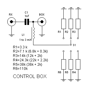
Here is the diagram and a picture of the control box :
Each operator can switch his receiver to one of the six Beverages, without interfering on the other receiving stations, with the help of the control box close to his operating position.
The control box is connected between the receiver and the spliting box. It is nothing more than a very ordinary 6 position rotary switch with 6 resistors. It is connected to the spliting box by the help of a 50 Ohms coaxial cable on any length.
The spliting box has 3 identical boards in it, one for each band.
On one side of the box, there are 3 RF connectors going to the 3 receivers (160m, 80m, 40m) and on the other side there are 6 RF connectors going to the 6 Beverage antennas.
All boards are connected to the 6 RF connectors in parallel.
The spliting box is power supplied by the main.
The need of the bandpass filter is to isolate each receiver input from the other. The antenna switch is build around a LM3914 voltage comparator and 6 small relays. In the control box, a voltage is made variable in 6 steps by the mean of a voltage divider and is feeded to the signal input of the LM3914.
The fixed part of the divider is in the spliting box and the variable part in the control box.
Depending of the position of the switch of the control box, a different output of the LM3914 is selected which activates a relay, and so a different antenna.
Here the LM3914 data sheet in PDF format.
Below is the drawing of the 160m spliting board.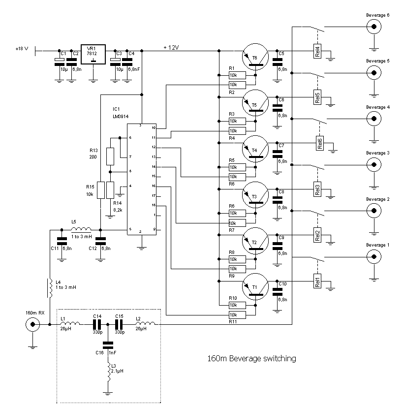
The 80m and 40m boards are identical, except the components inside the doted box which represents the bandpass filter.
The 3 boards are mounted close one to the other, the antenna inputs are connected together. Beverage 1 of 160m board is connected to Beverage 1 of 80m board and to Beverage 1 on 40m board, same for all inputs.
The 3 bandpass filters must be built in shielded boxes. No printed boards are necessary, they are "air" wired.
Band filters
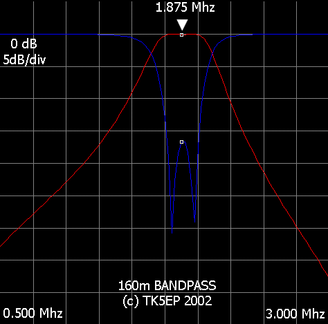
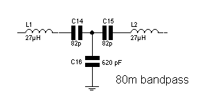
Click here to see the curve
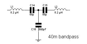
Clik here to see the curve
FAQ :
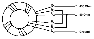
Q: How do i match my Beverage antenna to my 50 Ohm line ?
Well, the standard impedance of a Beverage antenna is close to 450 Ohm. So you need to make a 9:1 transformer to drop this impedance to your 50 Ohm.
You can do that easily with the help of a ferrite core like this :
Q : I find the reception is low, can i use a preamplifier ?
Yes you can, even if not necessary. The signal strength is often lower than with a dipole or a vertical but the signal to noise ratio (S/N) should be excellent. The preamplifier used should have a very good IP3, or intermodulation should appear.
Here a page with a preamplifier that can be used with Beverage antennas : http://w7iuv.com
Q : Can i use the bandpass filters for something else ?
Yes, for sure ! The filters have been designed for 50 ohm impedance and can be used in RX front-end, preamplifiers etc... Their diagrams are given in the doted boxes. They should be built in shielded boxes.
Links to Beverage antenna related pages:
http://www.qsl.net/aa3px/design.html
http://www.yccc.org/Articles/ka1gj_bev.htm
Pse mail me if you find errors.
73, Patrick TK5EP


