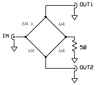
Ilt is sometimes necessary to split the output of one transmitter in order to drive 2 amplifiers or 2 antennas. There are several ways to do that, but an elegant one is to use this splitter.
The following description is the fruit of my own experience and works perfectly.
This splitter is composed of 4 lengths of 75 Ohm coaxial cable.
During normal operation, the injected power in the input IN and split in 2 equal levels on outputs OUT1 and OUT2.
No power should be present on the 50 Ohm dummy load.
The signal available on ouput OUT2 (via a Λ/4 line) has a -90° phase, the one on OUT1 (via the 3Λ/4 line) has a phase of -270°. The signal arriving into the dummy load (via the 3Λ/4 + Λ/4 and Λ/4 +Λ/4 lines) has a phase of 180°, so is cancelled !
One advantage of this splitter is that the 2 outputs are insulated one from the other !
In case of a mismatch on one of the outputs, the other output is not (or very slightly ) affected. All the power normaly present into the output is dissipated into the dummy load. This later one should be able to safely handle half the input power.
This circuit can be used on any frequency, you only need to cut the lines to the right length.
CAUTION, the lines have to be made in 75 Ohm coaxial cable !!. Don't forget to apply the velocity factor (depends of the isolating material) when you cut your lines !
This circuit can be used in a reversed manner, for example when you want to couple 2 amplifiers into one output. In this case, the splitter is used in a reversed manner, OUT1 and OUT2 are respectively IN1 and IN2, and the output is on IN.
CONS
Works only on one frequency/band...
A bit large, coaxial lines can be long...
I hope this can be useful for you ...

